Multi-channel signal wireless transmission system and physical resource grid distribution control method

A technology of wireless transmission and physical resources, applied in the field of nuclear magnetic resonance medical imaging equipment, can solve the problems of bulky circuits, coaxial cables occupying a large space, and limited service life, so as to avoid channel characteristic differences and signal distortion and distortion, and save Processing power consumption, clear and concise effect of division

Active Publication Date: 2020-12-01
YIKANG CLOUD INTELLIGENT TEGHNOLCGY CO LTD
View PDF12 Cites 4 Cited by
  • Summary
  • Abstract
  • Description
  • Claims
  • Application Information

AI Technical Summary

Problems solved by technology

[0008] 1. The front-end processing of analog signals requires the design of complex and cumbersome circuits to ensure distortion-free transmission under different gain conditions (flat amplitude-frequency characteristic curve and fixed group delay of phase-frequency characteristic curve), which leads to the production cost of MRI equipment Extremely high, the production efficiency is reduced, and the consistency between individual devices becomes poor;
[0009] 2. It is necessary to perform channel selection (RCCS) on the receiving coil signal, and a large number of RF radio frequency switch arrays are used. This method will cause distortion and damage to the transmission of analog signals, and will also introduce more noise interference;
[0010] 3. The connector between the receiving coil and the system (such as a hospital bed) needs: special structure and surface treatment without distortion transmission (such as gold plating), and because the connector has many contact points (pins, gold fingers and other contact methods), so The cost is expensive and the service life is limited;
[0011] 4. The layout of coaxial cables takes up a lot of space and introduces additional overhead (EMC / EMI) for electromagnetic compatibility compliance. In order to reduce the number of coaxial cables, it is necessary to use frequency division multiplexing to introduce mixers to achieve simulation The spectrum shift of the signal further increases the cost and introduces more distortion and noise interference;
[0012] 5. During the operation of the nuclear magnetic resonance imaging equipment, it is impossible to dynamically synthesize the signals of each receiving coil in terms of amplitude and phase in the form of software

Method used


Image

  • Multi-channel signal wireless transmission system and physical resource grid distribution control method
  • Multi-channel signal wireless transmission system and physical resource grid distribution control method
  • Multi-channel signal wireless transmission system and physical resource grid distribution control method

Examples


Embodiment 1

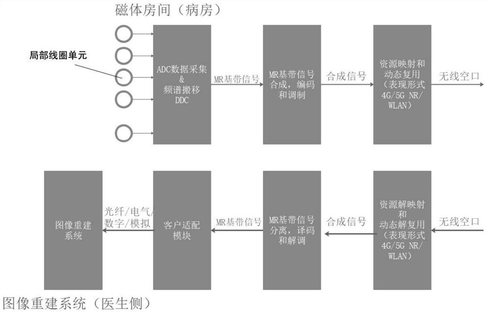
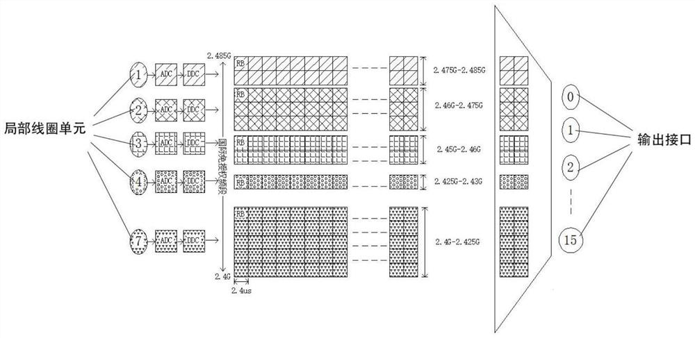
[0067] The present invention provides a multi-channel signal wireless transmission system for a nuclear magnetic resonance medical imaging system, specifically a multi-channel MR signal based on wireless communication network 4G LTE / 5G New Radio / WLAN WIFI and software-defined radio SDR technology wireless transmission systems such as figure 1 As shown, the present invention includes a transmitter and a receiver. When the system transmission link is an uplink, the uplink is the wireless transmission of MR magnetic resonance signals from the magnet room (ward) to the image reconstruction system (doctor side). Such as figure 1 As shown, the transmitter includes a local coil unit, a physical resource grid mapping unit module, an analog-to-digital conversion module, a digital down-conversion module, a synthesis and modulation module, and a receiver includes a wireless receiving module, a synchronization module, a demodulation module, and an output interface. The physical resource ...

Embodiment 2

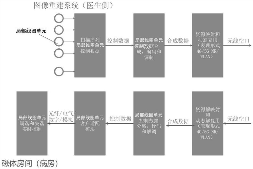
[0112] This embodiment corresponds to Embodiment 1. The transmission link of the system is a downlink. When the system transmission link is a downlink, the downlink is a real-time control signal for tuning and detuning required by the MR local coil. From the image Rebuild the system (doctor side) to the magnet room (patient room). Such as figure 2 As shown, the transmitter includes a local coil unit, a physical resource grid mapping unit module, a scanning sequence module, a synthesis and modulation module, and the receiver includes a wireless receiving module, a synchronization module, a demodulation module, and an output interface.

[0113] The scan sequence module is used to scan real-time control signals for the desired tuning and detuning of the local coil.

[0114] The difference from Embodiment 1 is that the dedicated subchannels designated by the physical resource grid are used for demodulation reference signals, phase tracking reference signals, and sounding referen...


PUM


Abstract

The invention provides a multi-channel signal wireless transmission system and a physical resource grid distribution control method. The multi-channel signal wireless transmission system comprises a transmitter and a receiver. The transmitter comprises a local coil unit, a physical resource grid mapping unit module, a signal collection module, a synthesis and modulation module and a mapping module, and the receiver comprises a wireless receiving module, a synchronization module and a demodulation module. The local coil unit is used for outputting an interface and acquiring signals. The signalcollection module is used for collecting signals. The synthesizing and modulating module is used for synthesizing and modulating the acquired signals. The mapping module is used for mapping the modulation signal. The synchronization module is used for synchronizing the modulated signals. The demodulation module is used for demodulating the synchronized signals. According to the system provided bythe invention, real-time acquisition, front-end processing, frequency spectrum shifting, virtual ID air interface channel selection, receiving coil tuning, detuning real-time control and the like canbe carried out on 1-128 paths of nuclear magnetic resonance signals at the same time, the framework of the system is simplified, the production cost is low, and the production efficiency is high.

Description

technical field [0001] The invention relates to the technical field of nuclear magnetic resonance medical imaging equipment, in particular to a multi-channel signal wireless transmission system and a control method for grid allocation of physical resources. Background technique [0002] In the MRI system, atomic nuclei can change from a high-energy state to a low-energy state in a non-radiative manner. This process is called relaxation. There are two types of relaxation: longitudinal relaxation and transverse relaxation. The NMR signal receiving system is very important. Its function is to receive the energy released by the relaxation in the form of electromagnetic waves for later image reconstruction of the system. International and domestic manufacturers, the current MRI equipment, the transmission link of the receiving system involves the following processes: [0003] 1. Weak analog signal front-end processing (low noise amplifier LNA, variable gain amplifier VGA) [00...

Claims


Application Information

Patent Timeline
Patent Type & Authority Applications(China)
IPC IPC(8): H04L27/26H04W72/04H04L27/00H04L5/00A61B5/055
CPCH04L27/2601H04L27/0014H04L5/0048H04L27/2657H04W72/0453H04L27/2662H04L5/003A61B5/055H04L2027/0026
Inventor 杜健军
Owner YIKANG CLOUD INTELLIGENT TEGHNOLCGY CO LTD
Why Eureka
Try Eureka