Check patentability & draft patents in minutes with Patsnap Eureka AI!

VOCs waste gas recovery treatment equipment and treatment process

A technology for waste gas recovery and treatment equipment, which is applied in gas treatment, vapor condensation, combined devices, etc., can solve the problems of short waste gas residence time, environmental pollution, and condenser tube damage, so as to improve condensation and liquefaction efficiency, increase residence time, increase The effect of high contact probability

Active Publication Date: 2020-12-04
浙江修格机械有限公司
View PDF3 Cites 3 Cited by
  • Summary
  • Abstract
  • Description
  • Claims
  • Application Information

AI Technical Summary

Problems solved by technology

[0004] 1. The residence time of VOCs exhaust gas passing through the traditional condenser is short, that is, the contact time between the gas and the condenser tube is short, and the gas passes through the condenser smoothly, making it difficult for VOCs to fully contact with the condenser tube, resulting in the inability of VOCs to be completely condensed Liquefaction, lower recovery rate of VOCs
[0005] 2. Since the VOCs exhaust gas may contain various types of organic substances such as benzene, ketones, lipids, ethers, etc., and the condensation temperatures required for various types of organic substances are different, resulting in only part of the VOCs exhaust gas passing through the condenser. Components are liquefied, other components are still discharged with the exhaust gas
[0006] 3. In addition to the gas components, the industrial waste gas is also mixed with some large solid particles and dust with small particle sizes. The large solid particles will cause damage to the inside of the condensing tube and the condenser, and the particles are easily deposited on the inner wall of the condensing tube and the condenser. The performance of the condenser, and the exhaust gas containing dust discharged into the air will also pollute the environment

Method used


Image

  • VOCs waste gas recovery treatment equipment and treatment process
  • VOCs waste gas recovery treatment equipment and treatment process
  • VOCs waste gas recovery treatment equipment and treatment process

Examples


Embodiment Construction

[0044] The present invention will be further described below in conjunction with the accompanying drawings.

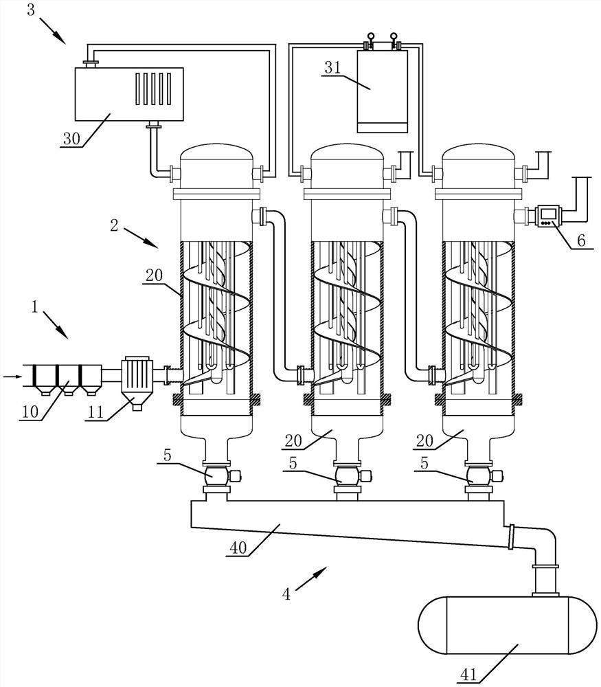
[0045] Such as figure 1 The shown VOCs waste gas recovery and treatment equipment includes a pretreatment device 1, a condensation tank group 2, a refrigerant liquid supply device 3 and a recovery device 4. The condensation tank group 2 includes three condensation tanks 20 arranged side by side, and the three condensation tanks 20 pass through The pipes communicate with each other; the refrigerant liquid supply device 3 includes a chiller 30 for providing circulating cold water to the first condensation tank 20 and two liquid nitrogen tanks for providing liquid nitrogen in the second and third condensation tanks 20 31.

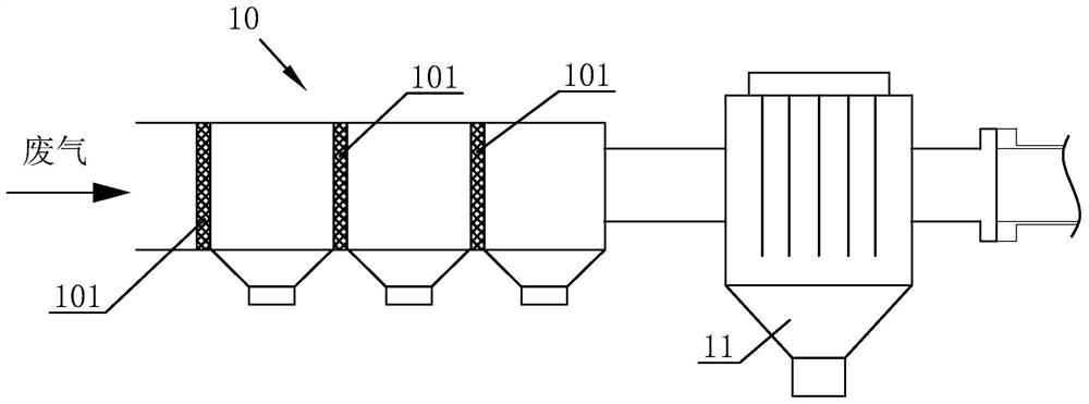
[0046] Such as figure 2As shown, the pre-processing device 1 includes a filter mechanism 10 and an electrostatic precipitator 11. The filter mechanism 10 includes three filter screens 101 with different mesh numbers. The filter screens 101 are arran...


PUM


Abstract

The invention discloses VOCs waste gas recovery treatment equipment and treatment process thereof; VOCs waste gas can be filtered and dedusted through pretreatment, the condensation efficiency is improved by increasing the residence time and confusion degree of the VOCs waste gas in a condensation tank, various components in the waste gas can be condensed and liquefied in a three-stage condensation mode, and the recovery rate of VOCs is increased. According to the treatment process, the VOCs waste gas recovery treatment equipment comprises a pretreatment device, a condensation tank group, a refrigerant fluid supply device and a recovery device, wherein the pretreatment device comprises a filtering mechanism and a dust removal mechanism; the condensation tank group comprises three condensation tanks which are communicated in sequence, wherein an inner cavity of at least one condensation tank is provided with a central condensation pipe and a spiral guide plate; the refrigerant fluid supply device comprises a cooling-water machine and a liquid nitrogen tank; the recovery device comprises a liquid flow channel and a liquid storage tank, and the bottom of the liquid flow channel is obliquely arranged. The VOCs waste gas recovery treatment process comprises the procedures of preparation, pretreatment, condensation, exhausting and recovery.

Description

technical field [0001] The invention relates to the field of condensation recovery devices, in particular to VOCs waste gas recovery and treatment equipment and a treatment process thereof. Background technique [0002] VOCs are a kind of volatile organic compounds, which are important precursors of urban haze and photochemical smog. They mainly come from coal chemical industry, petrochemical industry, fuel coating manufacturing, solvent manufacturing and other industries. VOCs exist in large quantities in industrial waste gas. VOCs have an unpleasant special smell, and are toxic, irritating, teratogenic and carcinogenic, especially benzene, toluene and formaldehyde will cause great harm to human health. [0003] With my country's increasing emphasis on the environment and the promotion of green production and green chemical policies, various industries have begun to devote themselves to more effective VOCs recovery and treatment solutions. At present, the commonly used rec...

Claims


Application Information

Patent Timeline
Patent Type & Authority Applications(China)
IPC IPC(8): B01D50/00B01D53/00B01D5/00
CPCB01D5/0003B01D50/00B01D53/002B01D2257/708
Inventor 龚熙阳
Owner 浙江修格机械有限公司
Features
  • R&D
  • Intellectual Property
  • Life Sciences
  • Materials
  • Tech Scout
  • Unparalleled Data Quality
  • Higher Quality Content
  • 60% Fewer Hallucinations
Learn More