Gas purification device

A gas purification device and gas treatment technology, applied in the direction of solid separation, chemical instruments and methods, external electrostatic separators, etc., can solve the problems of low efficiency and poor purification effect, and achieve good effect, high purification efficiency and high efficiency Effect

Pending Publication Date: 2020-12-04
成都市珑熙科技有限公司
View PDF0 Cites 0 Cited by
  • Summary
  • Abstract
  • Description
  • Claims
  • Application Information

AI Technical Summary

Problems solved by technology

[0004] The technical problem to be solved and the technical task proposed by the present invention are to improve the existing technology and provide a gas purification device to solve the problems of poor purification effect and low efficiency of the gas purification treatment device in the current technology

Method used


Image

  • Gas purification device
  • Gas purification device
  • Gas purification device

Examples


Embodiment 1

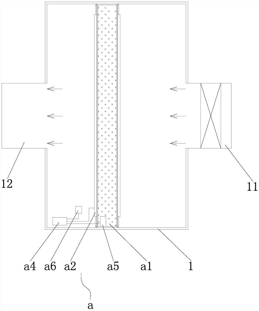
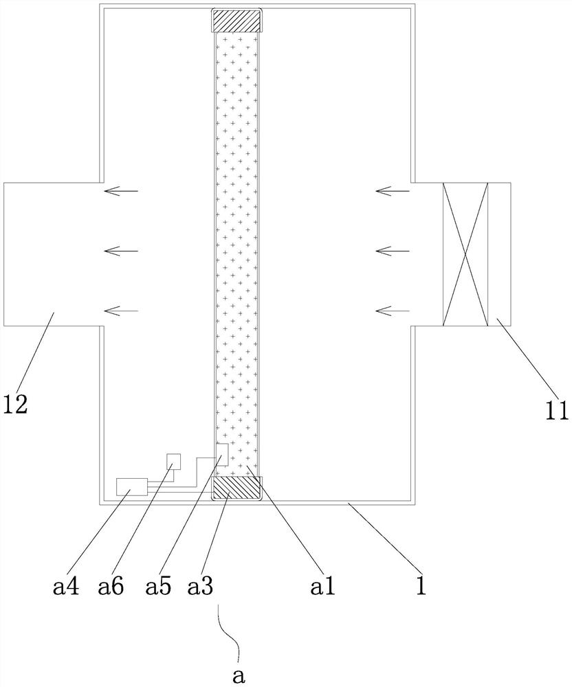
[0067] like figure 1 and figure 2 As shown, a gas purification device mainly includes a casing 1 and an activated carbon purification mechanism a set in the casing 1, the casing 1 is provided with an air inlet 11 and an air outlet 12, the activated carbon purification mechanism a It includes an activated carbon layer a1 and a temperature control assembly for controlling the temperature of the activated carbon layer a1. When the gas to be treated flowing from the shell 1 passes through the activated carbon layer a1 for adsorption and purification treatment, the temperature control assembly controls the activated carbon layer. a1 is at the first temperature, and the first temperature is higher than the dew point temperature of the gas to be treated. A fan can be installed in the casing 1 to make the gas inhaled from the air inlet 11, and then flow through the casing and pass through the activated carbon layer a1 , and finally discharged from the air outlet 12 , or an external ...

Embodiment 2

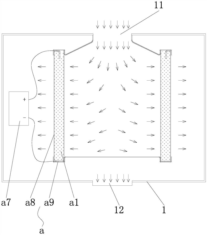
[0076] like image 3As shown, the difference from the first embodiment is that the temperature control component adopts a temperature control power supply a7, and the temperature control power supply a7 is electrically connected to the activated carbon layer a1 to energize the activated carbon layer a1, and the resistance of the activated carbon layer a1 is very large, The conductivity is relatively low, and the activated carbon layer a1 can heat itself when a low-voltage current is applied to the activated carbon layer a1. Different from using an additional heat source to conduct heat conduction to the activated carbon layer, this embodiment adopts the method of electrification to make the activated carbon layer a1 self-heating , the implementation is more convenient and simple, the structure is more compact, the energy utilization rate is high, and the power consumption is low.

[0077] In this embodiment, the activated carbon layer a1 has a cylindrical structure, the two ax...

Embodiment 3

[0080] like Figure 4 As shown, the shell 1 is provided with an activated carbon purification mechanism a and an electrostatic purification mechanism b, and the electrostatic purification mechanism b and the activated carbon purification mechanism a are sequentially arranged along the direction of the airflow in the shell. The treatment gas is ionized and the pollutants are charged. Under the action of the electric field force, it moves to the electrode of the electrostatic field and adheres to the electrostatic electrode to be deposited to realize the separation of the pollutant and the gas. First, the electrostatic unit is used to effectively remove the pollutants with large particle size. , can reduce the purification treatment pressure of the subsequent activated carbon layer, reduce the occurrence of clogging of the activated carbon layer, ensure the smoothness of air flow, enable the entire purification process to be carried out stably, and ensure the purification effect....


PUM


Abstract

The invention discloses a gas purification device, which comprises a shell and an activated carbon purification mechanism, wherein a gas inlet and a gas outlet are formed in the shell; the activated carbon purification mechanism is arranged in the shell and comprises an activated carbon layer and a temperature control assembly used for controlling the temperature of the activated carbon layer, andwhen gas to be treated flowing through the shell penetrates through the activated carbon layer to be subjected to adsorption purification treatment, the temperature control assembly controls the activated carbon layer to be at a first temperature, the first temperature is higher than the dew point temperature of the gas to be treated. According to the gas purification device disclosed by the invention, gas is adsorbed and purified by utilizing the activated carbon under the condition that the temperature is higher than the dew point, so that moisture-containing gas can be effectively prevented from being condensed when passing through the activated carbon layer, micropores of the activated carbon layer are prevented from being blocked by liquid generated by condensation, good adsorption activity and smoothness of the activated carbon layer are guaranteed, and the purification effect is guaranteed.

Description

technical field [0001] The present invention relates to the technical field of gas purification treatment, in particular to a gas purification device. Background technique [0002] In daily production and life, there are many activity scenarios that generate harmful gases. The direct emission of harmful gases causes serious environmental pollution. Therefore, it is usually necessary to purify the gases to reduce pollution and meet the requirements of green environmental protection. Cooking is an important part of daily life. Cooking will produce a lot of oil fume. Oil fume is the oil, organic matter and its thermal decomposition or cracking products volatile during food cooking and processing. The mixture generated by the reaction, the oil fume contains a variety of toxic and harmful components, and the components are very complex. There are not only organic flue gas generated by the physical and chemical reaction of oil, protein and raw materials under heating conditions, b...

Claims


Application Information

Patent Timeline
Patent Type & Authority Applications(China)
IPC IPC(8): B01D53/04B03C3/014B03C3/017B03C3/06B03C3/78
CPCB01D53/0407B03C3/014B03C3/017B03C3/06B03C3/78
Inventor 肖仁旺
Owner 成都市珑熙科技有限公司
Why Eureka
Try Eureka