
High-integration complete machine device of microscope objective

A high-integration, microscopic objective lens technology, applied in the direction of microscopes, photo-plate-making process exposure devices, installation, etc., can solve the problems of complex structure, difficulty in application, lack of overall planning of adjustment links, etc., and achieve the effect of high optical performance

Active Publication Date: 2020-12-04
CHANNGCHUN CHANGGUANG ADVANCED OPTICS TECH CO LTD
View PDF16 Cites 1 Cited by
  • Summary
  • Abstract
  • Description
  • Claims
  • Application Information

AI Technical Summary

Problems solved by technology

The third aspect: While ensuring the high-throughput and high-precision characteristics of the objective lens, it must also be cost-effective and suitable for mass production. Therefore, the application field of the above-mentioned advanced optical system can no longer be satisfied with only the basic imaging function. Requirements for high integration of multiple features such as calibratable, easy alignment, and manufacturability
[0004] The existing design method of microscopic objective lens is only aimed at a single module of basic imaging, and usually adopts the method of stacking the lenses in the lens barrel one by one, lacks the adjustment link and the overall planning of the adjustable part, low precision, complex structure, and low integration. Low cost, low cost performance, difficult to apply to high-end precision advanced optical system applications

Method used


Image

  • High-integration complete machine device of microscope objective
  • High-integration complete machine device of microscope objective
  • High-integration complete machine device of microscope objective

Examples


Embodiment Construction

[0027] In order to more clearly illustrate the technical solutions in the embodiments of the present invention or the prior art, the following will briefly introduce the drawings that need to be used in the description of the embodiments or the prior art. Obviously, the accompanying drawings in the following description are only These are some embodiments of the present invention. Those skilled in the art can also obtain other drawings based on these drawings without creative work.

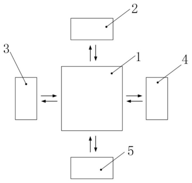
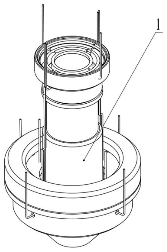
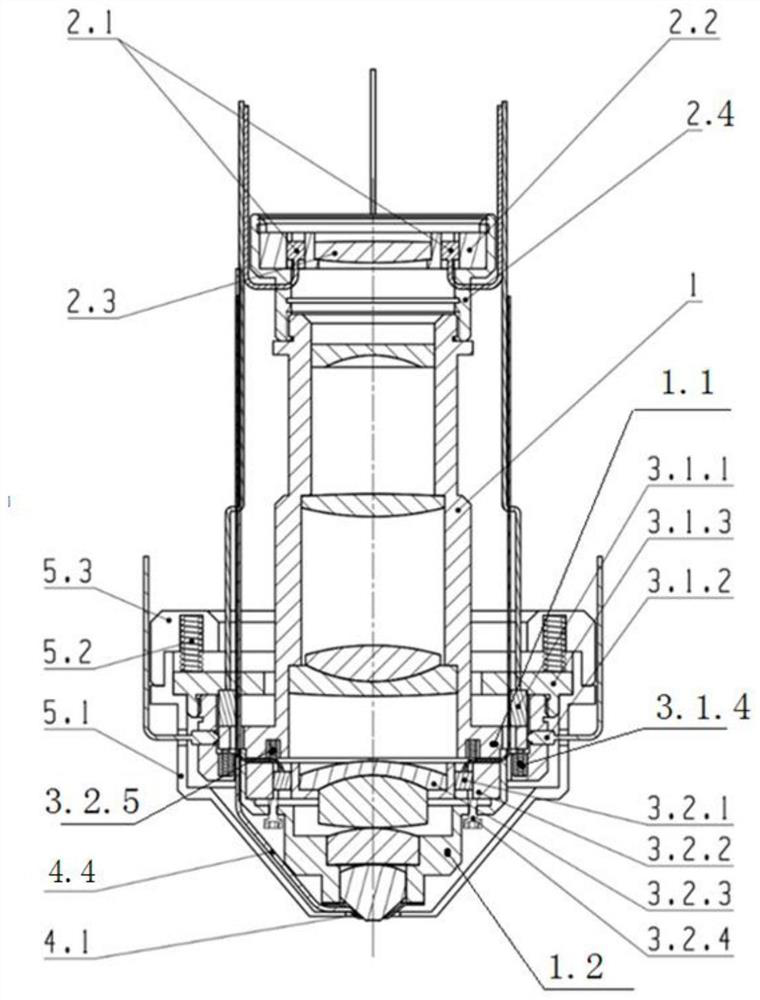
[0028] Such as figure 1 , 2 As shown, the highly integrated complete device of the microscope objective lens of the present invention includes five modules: the basic imaging objective lens main body 1, the zero position calibration device 2, the precise adjustment device 3, the immersion head assembly 4, and the objective lens anti-collision device 5.

[0029] Such as image 3 , 4As shown, the zero calibration device 2 is connected with the basic imaging objective lens main body 1 through scre...


PUM


Abstract

The invention relates to a high-integration complete machine device for a microscope objective. The lower part of a calibrator shell of the device is in threaded connection with the top of a basic imaging objective main body, and a zero adjustment flexible guide ring is embedded in the calibrator shell; piezoelectric drivers are uniformly distributed between the zero adjustment flexible guide ringand a calibration lens; the calibration lens is the first lens at the top end of the microscope objective in a basic imaging objective main body and shares the same optical axis with a basic imagingobjective; a multi-degree-of-freedom flexible guide ring in an accurate adjustment device is arranged in a lens shell at the lower part of a basic imaging objective lens main body, and a radial driveris arranged between the multi-degree-of-freedom flexible guide ring and a core lens group; an axial driver is in threaded connection with a mirror shell, and the top end of the axial driver abuts against the lower end of the multi-degree-of-freedom flexible guide ring. The device is high in integration degree, fine adjustment compensation can be carried out in the assembling and adjusting integration stage, the optical characteristics of the basic imaging body are adjusted in place, accurate positioning can be achieved through assistance of the zero calibrator in the whole machine integrationstage, and the precision loss in the integration stage is reduced to the minimum.

Description

technical field [0001] The invention belongs to the technical field of microscopic objective lenses, and relates to a highly integrated integrated device of a microscopic objective lens. Background technique [0002] As an advanced optical system, microscope objectives are widely used in the fields of biology, metrology, and semiconductor inspection. As human exploration continues to advance to more microscopic fields, there is an increasing demand for microscopic objectives. On the one hand: the objective lens is required to achieve high throughput. High throughput means that the objective lens system needs to have a large field of view, large Numerical aperture, wide spectrum and other characteristics, such as gene sequencing, wafer defect detection and other fields, all put forward high-throughput requirements for microscope objectives. On the other hand: the objective lens is required to achieve high precision, such as microscopic objective lenses used in fields such as...

Claims


Application Information

Patent Timeline
Patent Type & Authority Applications(China)
IPC IPC(8): G02B7/02G02B21/02G03F7/20
CPCG02B7/023G02B7/021G02B21/02G03F7/70341G03F7/70241
Inventor 管海军谢晓麟张新张继真
Owner CHANNGCHUN CHANGGUANG ADVANCED OPTICS TECH CO LTD
Learn More