A sintering process for magnet production

A magnet and process technology, applied in the field of sintering process for magnet production, can solve the problems affecting the production efficiency of magnet sintering, uneven distribution of magnet intergranular phases, slow magnet heating speed, etc., to reduce slow heat dissipation process, reduce heat preservation time, The effect of improving productivity

Active Publication Date: 2022-05-17
安徽万磁电子股份有限公司
View PDF0 Cites 0 Cited by
  • Summary
  • Abstract
  • Description
  • Claims
  • Application Information

AI Technical Summary

Problems solved by technology

[0005] The purpose of the present invention is to provide a sintering process for the production of magnets. By using induction coils to directly heat the magnets and using electric heating wires to keep the environment in the sintering furnace warm, it solves the problems of slow magnet heating and Uneven heating and long heating time lead to uneven distribution of magnet intergranular phases and coarse grains, which affect the performance of magnets; by introducing cooled inert gas into the sintering furnace, the slow cooling speed of magnets is solved, which affects the sintering production of magnets efficiency problem

Method used


Image

  • A sintering process for magnet production
  • A sintering process for magnet production
  • A sintering process for magnet production

Examples


Embodiment 1

[0034] A sintering process for magnet production, specifically comprising the following steps:

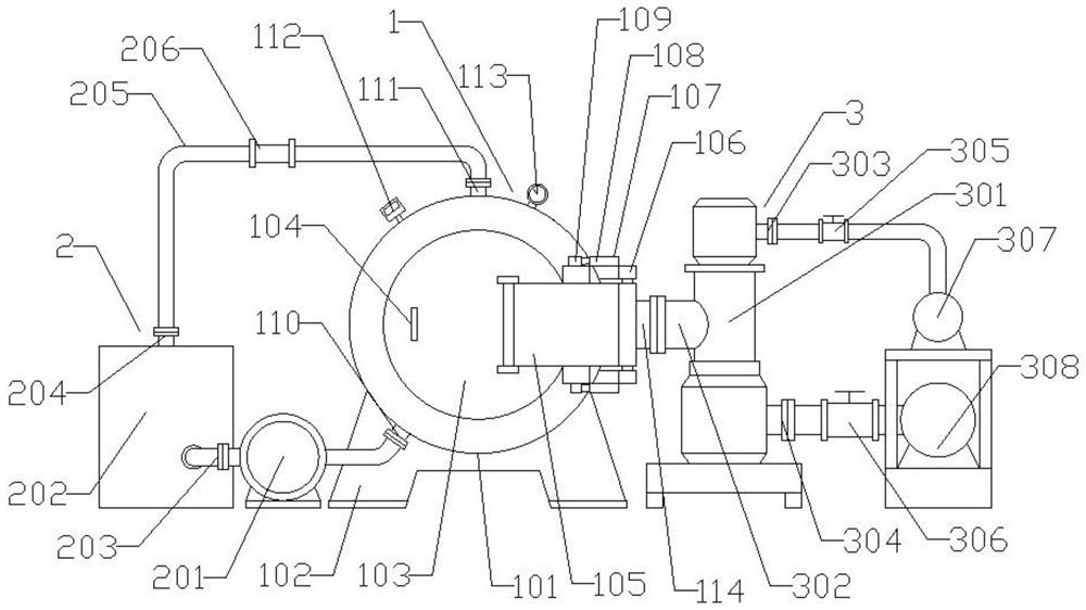
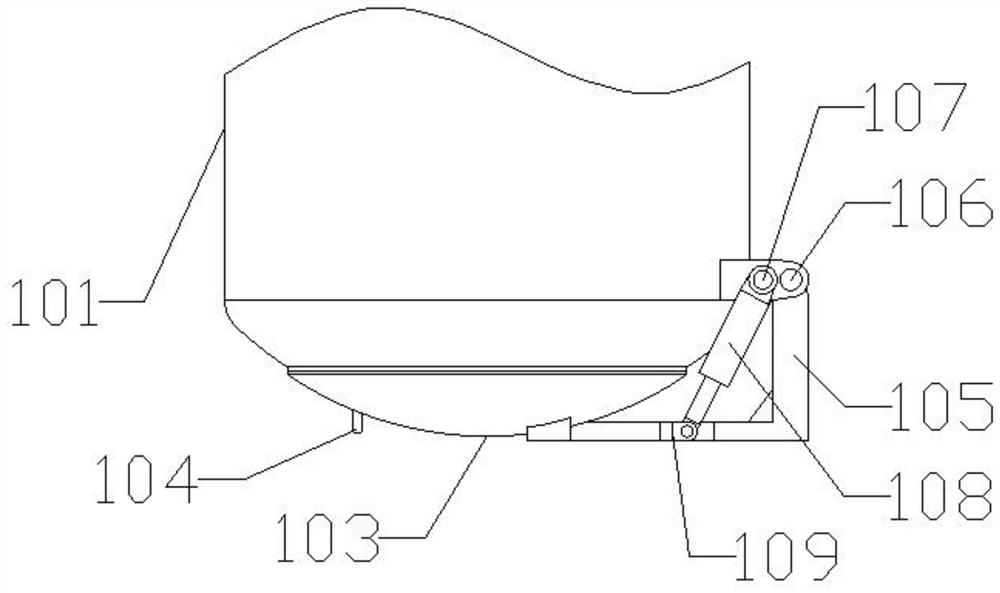
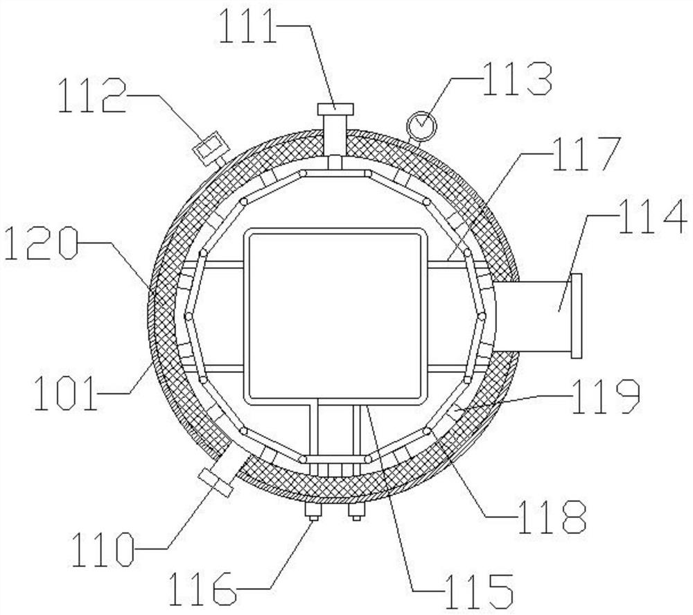
[0035] Step S1: Place the formed magnet compacts neatly in the induction coil 115 of the vacuum induction sintering furnace equipment according to a uniform gap, control the telescopic cylinder 108 to shrink, so that the furnace door 103 is closed and sealed, and at the same time start the first vacuum pump 308 and The second vacuum pump 307 pumps the vacuum inside the furnace body 101 to 2Pa, then closes the first valve 306 and the second valve 305, energizes the induction coil 115, and raises the temperature of the magnet compact from room temperature at a heating rate of 100°C / s To the first temperature of 300°C, keep warm for 8 minutes, open the first valve 306 during the heat preservation process, and evacuate the inside of the furnace body 101 to stabilize the vacuum degree at 50Pa;

[0036] Step S2: Heat the magnet treated in step S1 with the induction coil 115, and raise th...

Embodiment 2

[0040] A sintering process for magnet production, specifically comprising the following steps:

[0041] Step S1: Place the formed magnet compacts neatly in the induction coil 115 of the vacuum induction sintering furnace equipment according to a uniform gap, control the telescopic cylinder 108 to shrink, so that the furnace door 103 is closed and sealed, and at the same time start the first vacuum pump 308 and The second vacuum pump 307 pumps the vacuum inside the furnace body 101 to 4Pa, then closes the first valve 306 and the second valve 305, energizes the induction coil 115, and raises the temperature of the magnet compact from room temperature at a heating rate of 100°C / s To the first temperature of 350°C, keep warm for 9 minutes, open the first valve 306 during the heat preservation process, and evacuate the inside of the furnace body 101 to stabilize the vacuum degree at 50Pa;

[0042] Step S2: Heat the magnet treated in step S1 with the induction coil 115, and raise th...

Embodiment 3

[0046] A sintering process for magnet production, specifically comprising the following steps:

[0047] Step S1: Place the formed magnet compacts neatly in the induction coil 115 of the vacuum induction sintering furnace equipment according to a uniform gap, control the telescopic cylinder 108 to shrink, so that the furnace door 103 is closed and sealed, and at the same time start the first vacuum pump 308 and The second vacuum pump 307 pumps the vacuum inside the furnace body 101 to 5Pa, then closes the first valve 306 and the second valve 305, energizes the induction coil 115, and raises the temperature of the magnet compact from room temperature at a heating rate of 100°C / s To the first temperature of 400°C, keep warm for 10 minutes, open the first valve 306 during the heat preservation process, and vacuum the inside of the furnace body 101 to stabilize the vacuum degree at 50Pa;

[0048] Step S2: Heat the magnet treated in step S1 with the induction coil 115, raise the tem...


PUM


Abstract

The invention discloses a sintering process for magnet production, which specifically includes the following steps: step S1: heating up to the first temperature and keeping it warm, and discharging volatile substances in the magnet compact; step S2: heating up to the second temperature and keeping it warm, and discharging the magnet Gas impurities in the compact; step S3: heating up to the third temperature, sintering the magnet compact in a vacuum environment and keeping it warm; step S4: cooling the magnet with circulating inert gas gas quenching, and tempering the magnet. The present invention directly heats up the magnet by using the induction coil, and uses the electric heating wire to keep the environment in the sintering furnace warm, which solves the problem of slow magnet heating, uneven heating, and long heating time in the prior art, which leads to intergranular The problem of uneven phase distribution and coarse crystal grains affects the performance of the magnet; by passing the cooled inert gas into the sintering furnace, the problem of slow cooling of the magnet and affecting the production efficiency of the magnet sintering is solved.

Description

technical field [0001] The invention belongs to the technical field of magnet sintering equipment, and in particular relates to a sintering process for magnet production. Background technique [0002] Rare earth permanent magnet materials are the third generation of new functional materials developed in the 1980s. Rare earth permanent magnets are being rapidly developed and widely used for their excellent performance, abundant raw materials, and reasonable prices. It is mainly used in micro motors, permanent magnet instruments, electronics industry, automobile industry, petrochemical industry, nuclear magnetic resonance devices, electroacoustic equipment, magnetic levitation systems, magnetic transmission mechanisms and magnetic therapy equipment, etc. The main manufacturing processes of magnets are: alloy smelting, hydrogen crushing to make coarse powder, airflow grinding to fine powder, shaping, isostatic pressing, sintering, surface treatment, and magnetization. Among th...

Claims


Application Information

Patent Timeline
Patent Type & Authority Patents(China)
IPC IPC(8): H01F41/02B22F3/24B22F3/10
CPCH01F41/0253B22F3/1007B22F3/24B22F2003/248Y02P10/25
Inventor 唐睿韩幸奇尤晨晨
Owner 安徽万磁电子股份有限公司
Why Eureka
Try Eureka