Power grid flexible controller topology shared by modules

A controller and topology technology, applied in control/regulation systems, power transmission AC networks, AC networks with the same frequency from different sources, etc., to achieve the effects of saving costs, reducing power loss, and increasing transmission efficiency

Active Publication Date: 2020-12-11
SOUTHEAST UNIV
View PDF9 Cites 3 Cited by
  • Summary
  • Abstract
  • Description
  • Claims
  • Application Information

AI Technical Summary

Problems solved by technology

[0006] The purpose of the present invention is to address the shortcomings of the above-mentioned background technology and provide a grid flexible loop-closing controller topology shared by modules to meet the requirements of the distribution network for flexible controllers. The flexible loop-closing controller disclosed in the present invention can connect two Distribution network nodes with small voltage level and phase angle gap to realize power flow control of distribution network, improve power quality and power supply reliability, and solve the problem that although the existing flexible loop closing controller can realize the interconnection of distribution network nodes Technical problems at the expense of reducing efficiency and increasing costs

Method used


Image

  • Power grid flexible controller topology shared by modules
  • Power grid flexible controller topology shared by modules
  • Power grid flexible controller topology shared by modules

Examples


example 1

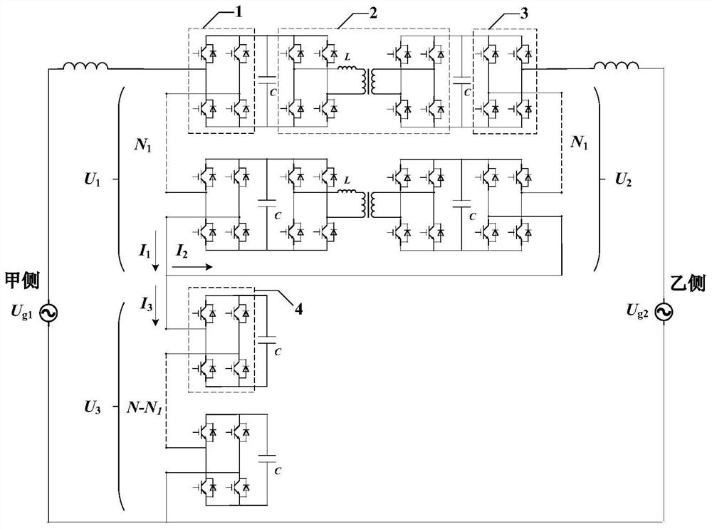
[0039] Single-phase flexible controller topologies such as figure 2 As shown, in this example, it is assumed that the two ports of the topology are connected to two 3.6kV AC networks with the same voltage amplitude and phase angle, and the connection function is verified through the simulation of the single-phase flexible controller topology. The main parameters of the simulation are shown in Table 1.

[0040] Table 1 Parameters of the flexible controller topology shared by modules under Example 1

[0041] parameter value parameter value Transmission powerP / kW 100 Output switching frequency / kHz 10 Input side voltage U g1 / V

3600 Filter inductance on both sides L / mH 10 Input side phase angle θ 1 / °

0 A-side module capacitor voltage U dc / V

750 Input side switching frequency / kHz 10 B-side module capacitor voltage U DC / V

750 Output side load R / Ω 64.88 Non-shared module full bridge number N 1

3 ...

example 2

[0047] The two ports are respectively connected to AC grids with voltage phase angles of 3.6kV, 0° and 3.7kV, 30°. The feasibility of the normal operation of the flexible controller topology is verified by means of vector diagrams when the power factor of the two ports of the flexible controller topology is 1. Assume that the specific parameters of the flexible controller topology are shown in Table 2.

[0048] Such as Figure 10 As shown, since it is assumed that the transmission power is determined and the phase angle of the voltage at both ends is determined, the AC current I of the input and output ports can be calculated through the transmission power 1 , I 2 The magnitude and phase angle of , so as to calculate the U 1 + U 3 , U 2 + U 3 amplitude and phase angle.

[0049] Since the AC voltage corresponding to the H bridge is smaller than the DC voltage corresponding to the H bridge, so U 1 , U 2 The corresponding maximum DC voltage amplitude U dc1,2 N is the pr...


PUM


Abstract

The invention discloses a power grid flexible controller topology shared by modules, and belongs to the technical field of power generation, power transformation or power distribution. Each single-phase topology comprises an AC / AC converter comprising N1 CHB modules and an AC / DC module comprising N-N1 full-bridge rectifiers, an AC port at one side of the AC / AC converter is formed after the AC input ends of the N1 CHB modules are connected in series, an AC port at the other side of the AC / AC converter is formed after the AC output ends of the N1 CHB modules are connected in series, AC input ends of the N-N1 full-bridge rectifiers are connected in series to form an AC port of the AC / DC module, an AC port at one side of the AC / AC converter is connected in series with the AC port of the AC / DCmodule and then is connected to a first AC power grid, and an AC port at the other side of the AC / AC converter is connected in series with a DC port of the AC / DC module and then is connected to a second AC power grid. According to the invention, the transmission efficiency of the whole flexible controller topology is improved by using the common module part. Meanwhile, compared with a common three-phase CHB structure, the flexible controller topology shared by the modules based on the cascaded H bridge has the advantage that the equipment cost and size are greatly reduced.

Description

technical field [0001] The invention relates to flexible controller technology, in particular to the topology of a flexible loop-closing controller for a power grid shared by modules, and belongs to the technical field of power generation, transformation or distribution. Background technique [0002] With the transformation of the global energy structure, the rapid increase in the proportion of renewable energy such as wind energy and solar energy has resulted in the increase of distributed power sources in the distribution network, and the structure of the distribution network system has become increasingly complex. At the same time, problems such as voltage over-limit and complex power flow in the distribution network cause power supply reliability and power quality to decrease. At present, the nodes of the distribution network are mainly connected by traditional mechanical switches. Due to the limitations of switching loss and inrush current, traditional mechanical switch...

Claims


Application Information

Patent Timeline
Patent Type & Authority Applications(China)
IPC IPC(8): H02J3/00H02J3/06H02J3/46H02J3/36H02M5/458H02M3/335
CPCH02J3/00H02J3/06H02J3/466H02J3/36H02M5/4585H02M3/33576H02J2203/10H02J2203/20H02J2300/40H02M1/0074H02M1/0077H02M5/225H02M7/4835H02M3/33584H02J3/26H02J3/46
Inventor 陈武何国豪
Owner SOUTHEAST UNIV
Why Eureka
Try Eureka