Continuous sludge pyrohydrolysis system and process capable of realizing efficient and sufficient pyrohydrolysis

A technology of thermal hydrolysis and sludge, which is applied in pyrolysis treatment of sludge, water/sludge/sewage treatment, multi-stage water treatment, etc. It can solve the problem of low thermal hydrolysis treatment efficiency of sludge and moisture content of dehydrated cake High, insufficient thermal hydrolysis and other problems, to achieve the effect of improving sludge treatment efficiency, increasing the degree of thermal hydrolysis, and good stability

Pending Publication Date: 2020-12-18
西安联创分布式可再生能源研究院有限公司
View PDF0 Cites 5 Cited by
  • Summary
  • Abstract
  • Description
  • Claims
  • Application Information

AI Technical Summary

Problems solved by technology

[0007] In view of the deficiencies in the prior art, the purpose of the present invention is to provide a continuous sludge thermal hydrolysis system and process capable of efficient and sufficient thermal hydrolysis, so as

Method used


Image

  • Continuous sludge pyrohydrolysis system and process capable of realizing efficient and sufficient pyrohydrolysis

Examples


Embodiment 1

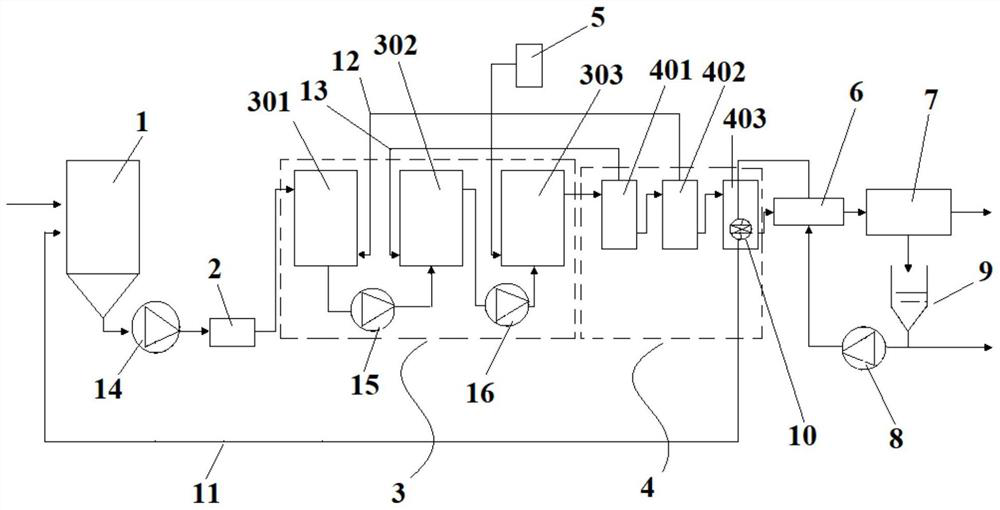
[0044] This embodiment provides a continuous sludge thermal hydrolysis system capable of efficient and sufficient thermal hydrolysis, such as figure 1 As shown, the system includes a sludge silo 1, the discharge port of the sludge silo 1 is connected with the grinding pump 2, and the grinding pump 2 is connected with the feed port of the slurry tank 301 in the step-by-step temperature boosting unit 3, The discharge port of the hydrolysis tank 303 in the step-by-step temperature boosting unit 3 is connected with the feed port of the multi-stage flash evaporation unit 4;

[0045] The step-by-step temperature boosting unit 3 includes a slurry tank 301, a preheating tank 302 and a hydrolysis tank 303 connected in sequence;

[0046] The multi-stage flash unit 4 includes a plurality of flash tanks connected in succession;

[0047] Hydrolysis tank 303 is also linked to each other with steam boiler 5;

[0048] The discharge port of the multi-stage flash evaporation unit 4 is connect...

Embodiment 2

[0054] This embodiment provides a continuous sludge thermal hydrolysis process capable of efficient and sufficient thermal hydrolysis, which adopts the continuous sludge thermal hydrolysis system capable of efficient and sufficient thermal hydrolysis given in Example 1;

[0055] In this process:

[0056] In the step-by-step temperature boosting unit 3, the temperature in the slurry tank 301 is increased to 85-90°C, and the pressure is normal pressure; the temperature in the preheating tank 302 is increased to 120-130°C, and the pressure is increased to 0.2MPa; the hydrolysis tank The temperature in 303 is increased to 180°C and the pressure is 1.0MPa.

[0057] In the step-by-step temperature boosting unit 3, the residence time of the sludge in the slurry tank 301, the preheating tank 302 and the hydrolysis tank 303 is 40 minutes.

[0058] The moisture content of the sludge in the sludge silo 1 is increased from 80% to 83%, the moisture content of the sludge in the slurry tank...

Embodiment 3

[0061] This embodiment provides a continuous sludge thermal hydrolysis process capable of efficient and sufficient thermal hydrolysis, which adopts the continuous sludge thermal hydrolysis system capable of efficient and sufficient thermal hydrolysis given in Example 1;

[0062] In this method, sludge with a water content of 80% is used as the thermal hydrolysis object, and the processing capacity is 2.5 tons per day, and the following steps are carried out:

[0063] Step 1, unload the sludge with a water content of 80% produced by sewage treatment into the sludge silo 1; start the centrifugal pump 9, and start the first screw pump 14, the second screw pump 15, the third screw pump 16 and the grinding pump at the same time 2;

[0064] Step 2, the centrifugal pump 9 heats part of the sludge press filtrate through the heat exchanger 6 and the triple flash heat exchanger 10 in the triple flash tank 403, and then enters the sludge silo 1 through the triple flash heat exchange tube...


PUM


Abstract

The invention provides a continuous sludge pyrohydrolysis system and process capable of realizing efficient and sufficient pyrohydrolysis, the system comprises a sludge bin, a discharge port of the sludge bin is connected with a grinding pump, the grinding pump is connected with a feed port of a slurrying tank in a step-by-step heating and boosting unit, and a discharge port of a hydrolysis tank in the step-by-step heating and boosting unit is connected with a feed port of a multi-stage flash evaporation unit; the step-by-step heating and boosting unit comprises the slurrying tank, a preheating tank and the hydrolysis tank which are connected in sequence; the multi-stage flash evaporation unit comprises a plurality of flash evaporation tanks which are connected in sequence; the hydrolysistank is also connected with a steam boiler; wherein a discharge port of the multi-stage flash evaporation unit is connected with a feed port of a heat exchanger, a discharge port of the heat exchangeris connected with a feed port of an automatic filter pressing system, and a discharge port of the automatic filter pressing system outputs dewatered mud cakes. According to the technology, the watercontent of the subsequent dehydrated mud cake can reach 50%, and compared with the water content of the subsequent dehydrated mud cake in the prior art of 60%, the water content of the subsequent dehydrated mud cake is reduced by 10%.

Description

technical field [0001] The invention belongs to the field of sewage treatment and relates to sludge pretreatment, in particular to a continuous sludge thermal hydrolysis system and process capable of efficient and sufficient thermal hydrolysis. Background technique [0002] Sludge thermal hydrolysis is a sludge pretreatment method. Its principle is to dissolve the microbial flocs in the sludge, cell rupture, and organic matter hydrolysis to reduce the solid particles of sticky sludge by heating and pressurizing in a pressure vessel. The binding effect on water fundamentally changes the water distribution characteristics of the sludge, and a large amount of intracellular water, capillary adsorption water and surface adsorption water are precipitated, so that more water in the sludge meets the requirements of mechanical dehydration, thereby improving the dehydration performance of the sludge . At the same time, the macromolecular organic matter in the cells is released and hy...

Claims


Application Information

Patent Timeline
IPC IPC(8): C02F11/10
CPCC02F11/10C02F2301/08
Inventor 徐世义吴飞蒋荣辉周向民
Owner 西安联创分布式可再生能源研究院有限公司
Why Eureka
Try Eureka