Hard coating cutter modulated in cathode magnetic field as well as preparation method and application thereof
A tool and coating technology, applied in the direction of tools for lathes, tools and coatings for milling machines, etc., can solve the problem of wear resistance, impact resistance and service life of tool substrates, and limit the thickness of hard protective coatings. , large residual compressive stress and other problems, to achieve long cutting life, solve the effect of limited increase in coating thickness and low production cost
- Summary
- Abstract
- Description
- Claims
- Application Information
AI Technical Summary
Problems solved by technology
Method used
Image
Examples
preparation example Construction
[0047] The preparation method of cutter is characterized in that, comprises the following steps:
[0048] Provide tool base;
[0049] Depositing a nitride coating on the tool substrate by physical vapor deposition arc ion plating;
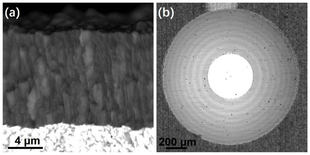
[0050] The low-stress layer has high-density "droplet" defects caused by a weak cathode magnetic field, and the high-stress layer has low-density "droplet" defects caused by a strong cathode magnetic field;
[0051] The target central magnetic field strength of the weak cathode magnetic field is 0.01Gs-50Gs, and the target central magnetic field strength of the strong cathode magnetic field is 100Gs-250Gs;
[0052] The density of the high-density "droplet" defects is >0.5 / square micron, and the density of the low-density "droplet" defects is <0.1 / square micron.
[0053] The method for preparing cutting tools in the present invention regulates the distribution of "droplets" in the coating through the cathode magnetic field, and combines the design...
Embodiment 1
[0070] After ultrasonic cleaning and drying of the cemented carbide tool substrate, it is sent into a coating furnace and argon gas is introduced. Under the conditions of a current of 150A, a bias voltage of -200V, and an air pressure of 3.0Pa, the ion source was used to perform ion etching on the tool substrate, and the etching time was 30min. Then adjust the cathode magnetic field, and alternately deposit high and low stress layers under the conditions of target current of 150A, bias voltage of -80V, and gas pressure of 2.0Pa to obtain a multilayer TiAlN coating. Open the TiAl target, when the magnetic field strength in the center of the target is 100Gs, deposit a high-stress TiAlN layer with a thickness of 0.65μm, and the deposition time is 15min; when the magnetic field strength in the center of the target is 20Gs, deposit a low-stress TiAlN layer with a thickness of 0.65μm , the deposition time is 20min. In this way, 8 alternating units are alternately deposited to obtai...
Embodiment 2
[0076] After ultrasonic cleaning and drying of the cemented carbide tool substrate, it is sent into a coating furnace and argon gas is introduced. Under the conditions of a current of 200A, a bias voltage of -300V, and an air pressure of 4.0Pa, the ion source was used to perform ion etching on the tool substrate, and the etching time was 20min. Then adjust the cathode magnetic field, and alternately deposit high and low stress layers under the conditions of target current of 200A, bias voltage of -100V, and gas pressure of 3.0Pa to obtain a multilayer CrAlN coating. Open the CrAl target, when the magnetic field strength in the center of the target is 50Gs, deposit a low-stress CrAlN layer with a thickness of 1.5μm, and the deposition time is 50min; when the magnetic field strength in the center of the target is 200Gs, deposit a high-stress CrAlN layer with a thickness of 0.5μm , the deposition time is 15min. In this way, 6 alternating units are alternately deposited to obtain...
PUM
| Property | Measurement | Unit |
|---|---|---|
| thickness | aaaaa | aaaaa |
| thickness | aaaaa | aaaaa |
| thickness | aaaaa | aaaaa |
Abstract
Description
Claims
Application Information
 - R&D
- Intellectual Property
- Life Sciences
- Materials
- Tech Scout
- Unparalleled Data Quality
- Higher Quality Content
- 60% Fewer Hallucinations
Browse by: Latest US Patents, China's latest patents, Technical Efficacy Thesaurus, Application Domain, Technology Topic, Popular Technical Reports.
© 2025 PatSnap. All rights reserved.Legal|Privacy policy|Modern Slavery Act Transparency Statement|Sitemap|About US| Contact US: help@patsnap.com


