
In-vitro artificial reflex arc structure and construction method and application thereof

A construction method and technology of reflex arc, applied in the field of tissue engineering, can solve the problems of affecting the nerve activity of muscle groups around the reflex arc, unable to carry out long-term research, affecting the function of the reflex arc and electrophysiological response, etc.

Active Publication Date: 2020-12-22
BEIJING INSTITUTE OF TECHNOLOGYGY
View PDF4 Cites 2 Cited by
  • Summary
  • Abstract
  • Description
  • Claims
  • Application Information

AI Technical Summary

Problems solved by technology

[0003] At present, research on reflex arcs is mainly based on invasive measurements of live animal models. The disadvantages include: invasive operations will affect the muscle groups or nerve activity around the reflex arc, which in turn will affect the function and electrophysiological response of the reflex arc, making long-term research impossible.

Method used


Image

  • In-vitro artificial reflex arc structure and construction method and application thereof
  • In-vitro artificial reflex arc structure and construction method and application thereof
  • In-vitro artificial reflex arc structure and construction method and application thereof

Examples


Embodiment 1

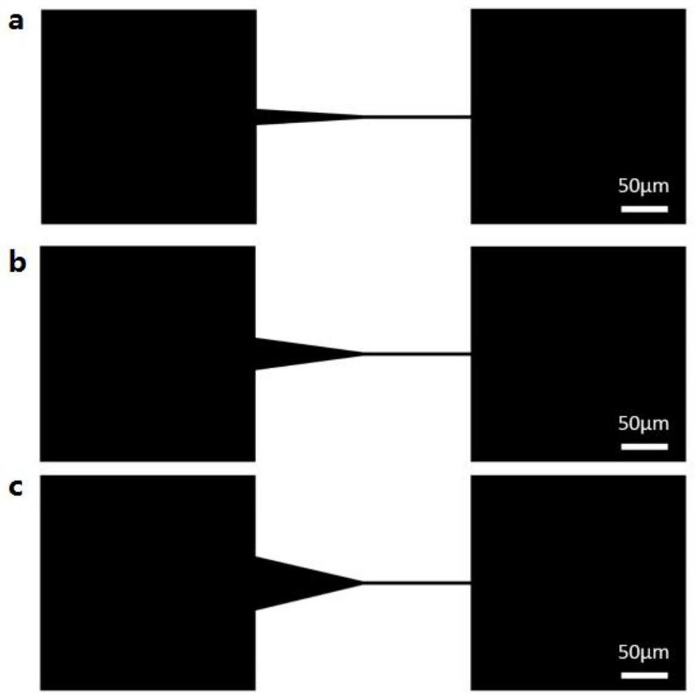
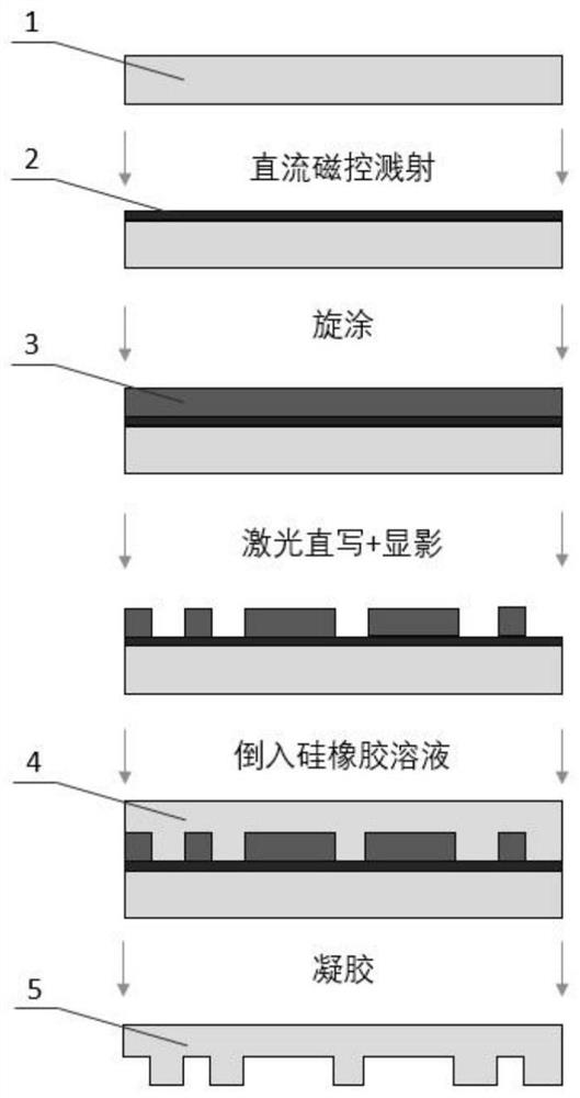
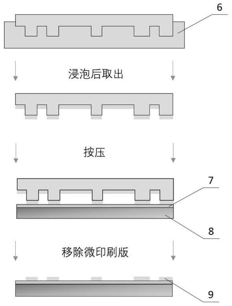
[0084] according to Figure 2-5 The flow chart shown constructs the artificial reflex arc structure in vitro, wherein, figure 2 Flowchart for the production of silicone rubber microprinting plate, image 3 Schematic diagram for microcontact printing, Figure 4 It is a schematic diagram of the structure of neurons cultured on the modified multi-electrode array culture dish, Figure 5 It is a flowchart of microcontact protein printing and neuron culture, in which, 1-soda glass substrate, 2-chromium nitride coating, 3-photoresist layer, 4-SYLGARD184, 5-silicone rubber microprinting plate, 6-adhesive Protein solution, 7- agarose coating, 8- petri dish for modified multi-electrode array, 9- microprotein pattern, 10- circular contact for multi-electrode array, 11- base for multi-electrode array, 12- dissected get of sensory neurons, 13 - sensory neurons with outstretched axons.

[0085] (1) Mask generator based on laser direct writing to directly prepare master

[0086] (1-1) ...

Embodiment 2

[0101] The in vitro artificial reflex arc-like structure was prepared according to the method of Example 1, the difference from Example 1 was that the maximum width of the thick section of the axon extension connection part in step (1-2) was 30 μm.

Embodiment 3

[0103] The in vitro artificial reflex arc-like structure was prepared according to the method of Example 1, the difference from Example 1 was that the maximum width of the thick section of the axon extension connection part in step (1-2) was 50 μm.


PUM

PropertyMeasurementUnit
thicknessaaaaaaaaaa
thicknessaaaaaaaaaa
sizeaaaaaaaaaa

Abstract

The invention provides an in-vitro artificial reflex arc structure and a construction method and application thereof, and belongs to the technical field of tissue engineering. The in-vitro artificialreflex arc structure which is clear in neuron network structure and high in signal propagation reliability is constructed in vitro by combining the advantages of high structural precision of a micro-protein pattern method based on micro-contact printing and stable formation of cultured synaptic connection; neuron axon extension is restrained and guided by utilizing a one-way threshold unit micro-protein mask pattern, so that the threshold value and direction of signal propagation in the in-vitro artificial reflex arc structure are controllable; micro-contact printing is carried out by adoptinga micro-mechanical arm, so that the requirement on the operation method is reduced, and the protein pattern is stable in formation; and the characteristic that the one-way threshold unit micro-protein mask pattern allows growth of dense neuron cell populations is utilized, so that an additional neuroglial cell layer does not need to be added to serve as a nutrient supporting layer of neurons during culture, the culture requirement of the in-vitro artificial reflex arc structure is greatly reduced, and the culture process is simplified.

Description

technical field [0001] The invention relates to the technical field of tissue engineering, in particular to an in vitro artificial reflex arc structure and its construction method and application. Background technique [0002] Humans or various vertebrates have some innate unconditioned reflexes, such as the eyeblink reflex caused by stimulating the cornea, the classic knee jerk reflex, and pupil constriction when exposed to light. From the perspective of species evolution, these unconditioned reflexes are important conditions for the continuation of humans and various vertebrates. Therefore, it is of great significance to study the morphological and functional changes during the development and formation of the reflex arc, the carrier of unconditioned reflex, for understanding the working mechanism of unconditioned reflex and the structural basis of high reliability. [0003] At present, research on reflex arcs is mainly based on invasive measurements of living animal mode...

Claims


Application Information

Patent Timeline
Patent Type & Authority Applications(China)
IPC IPC(8): C12N5/0793C12Q1/02
CPCC12N5/0619G01N33/5005C12N2535/10
Inventor 石青陈喆梁倩孙韬王化平黄强福田敏男
Owner BEIJING INSTITUTE OF TECHNOLOGYGY
Learn More