Milling stability prediction method based on implicit exponential time-history difference multi-step method

A technology of stability prediction and multi-step method, which is applied in complex mathematical operations, electrical digital data processing, special data processing applications, etc., and can solve the problems of poor calculation accuracy and low calculation accuracy.

Pending Publication Date: 2020-12-25
HUNAN INST OF TECH
View PDF2 Cites 1 Cited by
  • Summary
  • Abstract
  • Description
  • Claims
  • Application Information

AI Technical Summary

Problems solved by technology

[0003] Currently, the literature "Jiang SL, Sun YW, Yuan XL, Liu WR. A second-order semi-discretization method for the efficient and accurate stability prediction of milling process. The International Journal of Advanced Manufacturing Technology, 2017; 92(1–4): 583–595” discloses a milling stability prediction method based on the second-order semi-discrete method, which uses the fine integration method to calculate the exponential matrix, which improves the calculation efficiency, but the calculation accuracy is very poor
The literature "Wu Y, You YP, Liu AM, Deng B, Liu W. An implicit exponentially fitted method for chatter stability prediction of milling processes. The International Journal of Advanced Manufacturing Technology, 2020, 106:2189–2204" discloses a method based on three Milling stability analysis method based on step exponential fitting method, which has high calculation efficiency but low calculation accuracy
In addition, the Chinese patent document "CN106843147A" discloses a method for predicting milling stability based on the Hamming formula, which has high computational efficiency but low computational accuracy

Method used


Image

  • Milling stability prediction method based on implicit exponential time-history difference multi-step method
  • Milling stability prediction method based on implicit exponential time-history difference multi-step method
  • Milling stability prediction method based on implicit exponential time-history difference multi-step method

Examples


Embodiment Construction

[0078] In order to facilitate those skilled in the art to better understand the improvement of the present invention relative to the prior art, the present invention will be further described below in conjunction with the accompanying drawings and embodiments.

[0079] In the following embodiment, the milling stability will be predicted based on the implicit exponential time history difference multi-step method, and the specific steps are as follows:

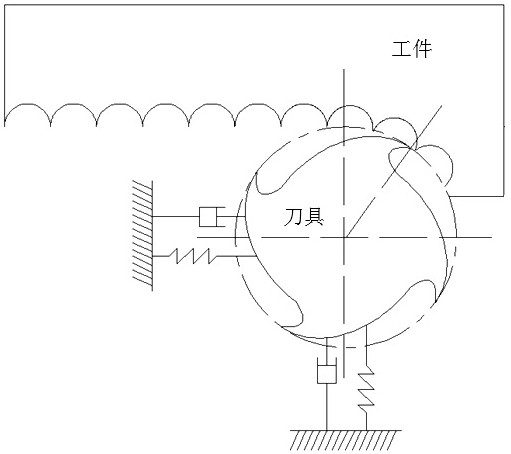
[0080] 1. Transform the time-delay differential dynamics equation of milling processing into the space state form considering the regeneration effect, and obtain the dynamics control equation of the milling system.

[0081] The time-delay differential dynamics equation of milling considering regeneration effect is:

[0082]

[0083] In formula (1), M, C, K, and q(t) are the modal mass matrix, modal damping matrix, modal stiffness matrix, and modal coordinates of the milling cutter in the milling system, respectively; t repres...


PUM


Abstract

A milling stability prediction method based on an implicit exponential time-history difference multistep method comprises the steps that a milling system is analyzed, a kinetic model is established, then a forced vibration stage is divided into a plurality of time intervals at equal intervals, discrete values at discrete points are solved through the implicit exponential time-history difference multistep method within each time interval, the state transfer matrix of the milling system in the adjacent periods is obtained, the characteristic value of the state transfer matrix is calculated, andthe stability of the milling system is judged according to the Floquet theory, so that the prediction precision and the calculation efficiency are improved, and therefore, proper process parameters can be optimally selected to improve the processing efficiency and reduce the production cost; specifically, in the high-speed cutting process of a numerical control precision machining center, reasonable cutting parameters are selected through a milling flutter stability lobe graph, flutter-free stable cutting machining is achieved, and better surface quality and machining precision are obtained.

Description

technical field [0001] The invention relates to the field of advanced manufacturing technology, in particular to a milling stability prediction method based on an implicit exponential time history difference multi-step method. Background technique [0002] With the development of high-precision and high-quality key parts in the field of machinery manufacturing such as aviation, aerospace and vehicles, more and more stringent requirements are put forward for the performance of CNC machine tools. As the most common and important machining technology, CNC milling has the advantages of small deformation, low milling force, high precision and high efficiency. However, the milling process is often accompanied by various vibrations, which will accelerate tool wear and Damage seriously affects the surface quality of the workpiece, greatly restricts the machining accuracy and efficiency, and makes it difficult for machine tools and tools to perform their functions. By predicting the...

Claims


Application Information

Patent Timeline
Patent Type & Authority Applications(China)
IPC IPC(8): G06F30/20G06F17/16G06F17/11G06F119/14
CPCG06F30/20G06F17/16G06F17/11G06F2119/14
Inventor 邓彬伍毅叶拓刘安民
Owner HUNAN INST OF TECH
Why Eureka
Try Eureka