
Light-driven micron sheet array motor system

A micron-chip, light-driven technology, applied in generators/motors, motors with thermal effects, electrical components, etc., can solve problems that limit the application of micro-motor systems, achieve high-efficiency light-to-mechanical energy conversion, enhanced coupling, and good application value effect

Inactive Publication Date: 2021-01-08
刘翡琼
View PDF0 Cites 0 Cited by
  • Summary
  • Abstract
  • Description
  • Claims
  • Application Information

AI Technical Summary

Problems solved by technology

Most of the existing micro motors are driven by ultrasonic waves or magnetic fields, which limits the application of micro motor systems

Method used


Image

  • Light-driven micron sheet array motor system
  • Light-driven micron sheet array motor system

Examples


Embodiment 1

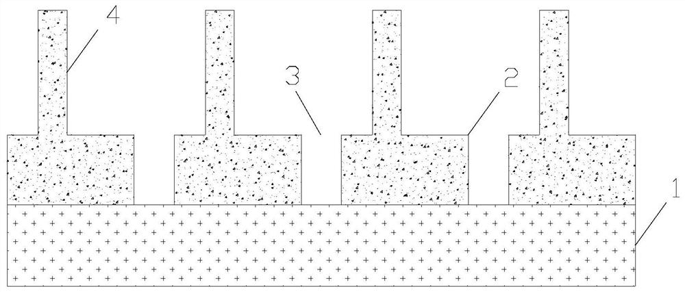
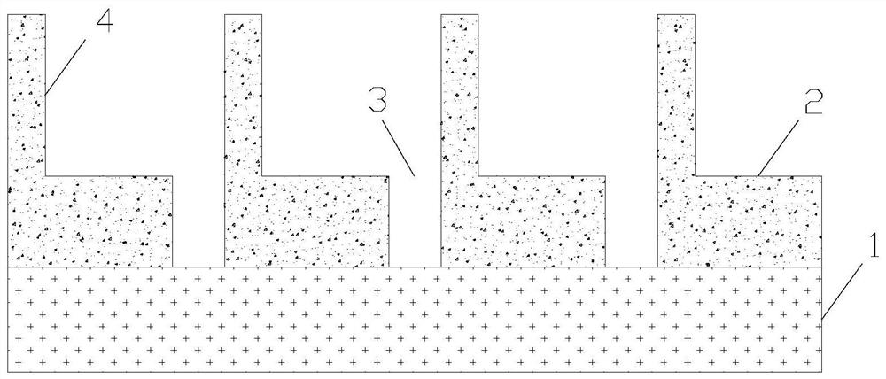
[0020] The invention provides a light-driven microchip array motor system. figure 1 It is a cross-sectional view of the light-driven microsheet array motor system of the present invention, such as figure 1 As shown, the light-driven microchip array motor system includes a substrate 1 , a noble metal layer 2 , a slit 3 , and a noble metal microchip 4 . The noble metal layer 2 is placed on the substrate 1 . The material of the base 1 is a transparent material. Preferably, the material of the substrate 1 is silicon dioxide. The slots 3 are periodically placed in the noble metal layer 2 . The noble metal micro-sheets 4 are vertically placed on the noble metal layer 2 , and the noble metal micro-sheets 4 are periodically and asymmetrically arranged between adjacent gaps 3 . figure 1 The noble metal microflake 4 in is the cross section of the noble metal microflake 4, that is to say, in figure 1 The horizontal direction in is the thickness direction of the noble metal microshee...

Embodiment 2

[0024] On the basis of Embodiment 1, the material of the substrate 1 is a non-transparent material, and the pulsed laser is irradiated from the side of the noble metal microsheet 4 . In this way, the contact area between the light and the micro-nano structure in the present invention is large, and the light can be more coupled into the cavity formed by the noble metal micro-sheet 4. Due to the asymmetric arrangement of the noble metal micro-sheet 4 relative to the slit 3, Stronger and different intensities of surface plasmon polaritons are generated on both sides of the noble metal micro-sheet 4 , thereby generating greater photothermal force on the noble metal micro-sheet 4 , thereby realizing higher-efficiency light-to-mechanical energy conversion.

[0025] Furthermore, the material of the substrate 1 is noble metal. The material of the substrate 1 is the same as that of the noble metal layer 2 or the noble metal microsheet 4 . In this way, the substrate 1 blocks the surfac...


PUM


Abstract

The invention provides a light-driven micron sheet array motor system, which is characterized in that a noble metal layer is arranged on a substrate, slits are periodically arranged in the noble metallayer, and noble metal micron sheets are vertically arranged on the noble metal layer, and are periodically and asymmetrically arranged between adjacent slits. During application, by using pulse laser irradiation, micron sheets are asymmetrically arranged between adjacent silts, and surface plasmon polariton intensities generated on the two sides of the noble metal micron sheets are different, sothat different heat is generated on the two sides of the noble metal micron sheets, and temperature gradients on the two sides of the noble metal micron sheets are caused to produce photothermal force so as to drive the noble metal micron sheets to swing. According to the invention, the light-driven micron sheet array motor system has the advantage of being high in light energy and mechanical energy conversion efficiency; and the noble metal micron sheet array is driven to swing, and the light-driven micron sheet array motor system has good application value in the fields of photocatalysis, environmental governance and the like.

Description

technical field [0001] The invention relates to the technical field of light-driven micro-motors, in particular to a light-driven micro-chip array motor system. Background technique [0002] Micro-motor systems have a wide range of applications in the fields of micro-nano machinery, clinical medicine, and environmental governance. Most of the existing micromotors are driven by ultrasonic waves or magnetic fields, which limits the application of micromotor systems. Contents of the invention [0003] In order to solve the above problems, the present invention provides a light-driven micro-chip array motor system, including a substrate, a noble metal layer, a slit, and a noble metal micro-chip. The noble metal layer is placed on the base, and the slits are periodically placed in the noble metal layer. The sheets are placed vertically on the noble metal layer, and the noble metal micro-sheets are periodically and asymmetrically arranged between adjacent gaps; in application, ...

Claims


Application Information

Patent Timeline
Patent Type & Authority Applications(China)
IPC IPC(8): H02N10/00
CPCH02N10/00
Inventor 不公告发明人
Owner 刘翡琼
Learn More