Zero-voltage switch forward direct-current direct-current converter and control method thereof

A zero-voltage switching, DC converter technology, applied in the direction of converting DC power input to DC power output, regulating electrical variables, control/regulating systems, etc. Effective resonance reset and other problems, to solve the EMI problem, easy compensation, good stability

Active Publication Date: 2021-01-15
杭州欧佩捷科技有限公司
View PDF7 Cites 8 Cited by
  • Summary
  • Abstract
  • Description
  • Claims
  • Application Information

AI Technical Summary

Problems solved by technology

[0005] Under the condition of discontinuous current mode, if the freewheeling duration of the output inductor current is less than the resonant reset time, the isolated output transformer cannot effectively resonantly reset due to the open circuit of the freewheeling diode D2
When the output current of the forward DC-DC converter is required to vary in a wide range, the forward DC-DC converter will inevitably work in the discontinuous current mode, and this resonant reset method cannot effectively ensure the isolated output Transformer Resonant Reset

Method used


Image

  • Zero-voltage switch forward direct-current direct-current converter and control method thereof
  • Zero-voltage switch forward direct-current direct-current converter and control method thereof
  • Zero-voltage switch forward direct-current direct-current converter and control method thereof

Examples


Embodiment 1

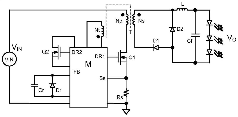
[0078] The block diagram related to the detection resistor Rc and MOS transistor Q2 inside the functional module M is as follows Figure 5 shown. The functional module M includes a resettable integrator (hereinafter referred to as integrator), a comparison + limiter error amplification module, and a zero-crossing + delay module. The source of the MOS transistor Q2 is connected to the ground through the detection resistor Rc. The drain of the MOS transistor Q2 is connected to the same terminal of the reset winding Nt. The non-identical end of the reset winding Nt is connected to the ground through the resonant capacitor Cr. The parallel diode Dr is connected in parallel with the resonant capacitor Cr, and the anode of the parallel diode Dr is grounded. The output of the comparison + limiter error amplifier module is connected to the gate of the MOS transistor Q2. The feedback voltage of the detection resistor Rc is respectively used as the input signal of the resettable int...

Embodiment 2

[0085] compared to Figure 5 Specifically, the function module M omits a resettable integrator, and the function module M includes a comparison + limiter error amplification module, and a zero-crossing + delay module. Specific as Image 6 shown. The source of the MOS transistor Q2 is grounded. The drain of the MOS transistor Q2 is connected to the same terminal of the reset winding Nt. The non-identical end of the reset winding Nt is connected to the ground through the resonant capacitor Cr. The parallel diode Dr is connected in parallel with the resonant capacitor Cr, and the anode of the parallel diode Dr is grounded. The output of the comparison + limiter error amplifier module is connected to the gate of the MOS transistor Q2. The voltage of the resonant capacitor Cr is fed back to the output voltage by the voltage divider network formed by Ru and Rd as the input signals of the comparison + limiter error amplification module and the zero-crossing + delay module respec...

Embodiment 3

[0096] The functional module M is placed on the secondary side of the output transformer and according to the circuit of the aforementioned embodiment 2 ( Image 6 ) is realized; thus the voltage divider network formed by the reset winding Nt, the MOS transistors Q2, Ru and Rd and the detection resistor Rs are all on the secondary side. The feedback voltage of the detection resistor Rs represents the output inductor current; the voltage divider network composed of Ru and Rd feeds back the voltage Vcr of the resonant capacitor Cr. The voltage divider network composed of Ru and Rd feeds back through the FB terminal of the functional module M to control the MOS transistor Q2 together with the functional module M. In order to control the primary side MOS transistor Q1 to be turned on by the ZVS switch, a functional module M1 is added to the primary side of the output isolation transformer. In this way, the output information of the functional module M is isolated and coupled to the...


PUM


Abstract

The invention discloses a zero-voltage switch forward direct-current direct-current converter which comprises a functional module M, an output isolation transformer, a primary side MOS transistor Q1 and an MOS transistor Q2; the output isolation transformer comprises a primary winding Np, a secondary winding Ns and a reset winding Nt, and the output isolation transformer is provided with an excitation inductor Lm; and the functional module M has the following two functions: one function is to control the conduction and cutoff of the primary side MOS transistor Q1, and the other function is tocontrol the conduction and cutoff of the MOS transistor Q2 according to the change of the resonance reset current or voltage. The invention further discloses a control method of the zero-voltage switch forward direct-current direct-current converter. No matter whether the output current is in an interrupted mode or a continuous mode, the output isolation transformer can be reset in a resonance mode.

Description

technical field [0001] The invention relates to a zero-voltage switch forward DC-DC converter and a control scheme thereof. Background technique [0002] In the flyback DC-DC converter, due to the effect of the output voltage, its isolation output transformer automatically completes the reset function, while in the forward DC-DC converter, it lacks the reset function of its isolation output transformer, and it needs to provide additional circuitry to help with reset. There are currently several reset methods that can be used, such as RCD circuits, reset windings, active degaussing resets, and resonant resets. Among them, the active degaussing reset and resonance reset can make the isolated output transformer work in the first and third quadrants. This is beneficial to further reduce the volume of the isolation output transformer. [0003] Active degauss reset (eg figure 1 shown) can also make the forward converter work in the zero-voltage switching (ZVS) conduction mode ...

Claims


Application Information

Patent Timeline
Patent Type & Authority Applications(China)
IPC IPC(8): H02M1/08H02M1/088H02M3/335H02M1/44
CPCH02M1/08H02M1/088H02M1/44H02M3/33569H02M1/0058Y02B70/10
Inventor 翁大丰孙建中
Owner 杭州欧佩捷科技有限公司
Why Eureka
Try Eureka