Rich oil debenzolization heating system

A heating system and oil-rich technology, applied in lighting and heating equipment, petroleum industry, heat exchanger types, etc., can solve the problems of poor site utilization, gas waste, poor economic benefits, etc., and achieve improved safety performance and economical operation. Cost and space saving effect

Pending Publication Date: 2021-01-29
SHAANXI ZIZHAO EQUIP MFG
View PDF0 Cites 0 Cited by
  • Summary
  • Abstract
  • Description
  • Claims
  • Application Information

AI Technical Summary

Problems solved by technology

[0002] In the industrial coal chemical system, the heating of the rich oil in the current oil-rich debenzene technology is to use a tube furnace to heat the rich oil. The combustion medium of the furnace is gas. The gas is burned in the furnace of the tube furnace. The flue gas after combustion contains harmful substances such as sulfur dioxide and nitrogen oxides. The sulfur content of coke oven gas is 100mg / m 3 , every cubic coke oven gas combustion produces 200mg of S0 2 , the gas combustion consumption per hour of the tube furnace is 2400m 3 , generating S0 every hour 2 is 0.48kg, and produces 4204kg of S0 per year 2 , each chemical plant has at least 4 such tube furnaces, so the emission S0 of a chemical plant tube furnace is calculated 2 It is 16.8 tons, and the flue gas after the combustion of the tube furnace in most coking plants is not purified, and is directly discharged through the chimney, polluting the environment, and the cost of treating the flue gas of the tube furnace is relatively high
Furthermore, the heating efficiency of the tube furnace is low, about 70%, a large amount of gas is wasted, and the economic benefit is poor.
The tube furnace uses coke oven gas as fuel and operates with an open flame. Coke oven gas itself is a flammable, explosive, and toxic medium. The operation is strictly in accordance with the operating procedures. Improper operation may easily cause fire and explosion accidents.
There is a strict safety distance between the tube furnace and Class A medium (crude benzene) and other equipment and buildings. In addition, the tube furnace equipment is large in size, occupies a large area, and has poor site utilization.

Method used


Image

  • Rich oil debenzolization heating system

Examples


Embodiment Construction

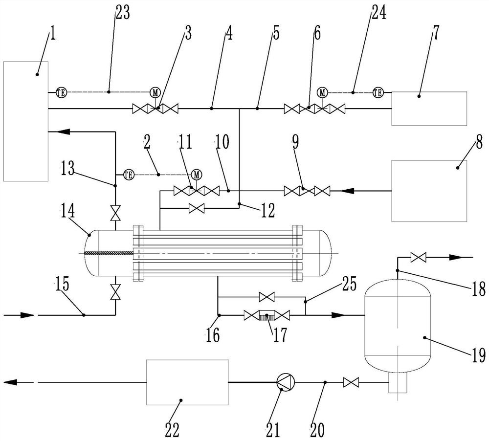
[0023] A kind of oil-rich debenzene heating system of the present invention is further described below in conjunction with accompanying drawing and specific embodiment:

[0024] figure 1 It is a schematic diagram of an oil-rich debenzene heating system of the present invention. In the figure, the oil-rich debenzene heating system includes a shell-and-tube heat exchanger 14. The heated fluid inlet of the shell-and-tube heat exchanger 14 is connected to an oil-rich inlet pipeline 15, and a shut-off valve is arranged on the oil-rich inlet pipeline 15. The heated fluid outlet of the shell heat exchanger 14 is connected to the oil-rich outlet pipeline 13, and the upper end of the oil-rich outlet pipeline 13 is connected to the debenzene tower 1. The oil-rich outlet pipeline 13 is provided with a temperature sensor and a shut-off valve. The heat transfer fluid inlet of the shell heat exchanger 14 is connected to the superheated steam pipe 10, the right end of the superheated steam...


PUM


Abstract

The invention discloses a rich oil debenzolization heating system which comprises a heat exchanger, a heated fluid inlet of the heat exchanger is connected with a rich oil inlet pipeline, a heated fluid outlet of the heat exchanger is connected with a rich oil outlet pipeline, the other end of the rich oil outlet pipeline is connected to a debenzolization tower, and a temperature sensor is arranged on the rich oil outlet pipeline. A heat transfer fluid inlet of the heat exchanger is connected with a superheated steam pipeline, the other end of the superheated steam pipeline is connected with asteam boiler, a heat transfer fluid outlet of the heat exchanger is connected with a condensed water pipeline, and the other end of the condensed water pipeline is connected to a low-pressure flash tank. The heating system is small in occupied area, safe and environmentally friendly, sulfur, nitric oxide and other return gas are not generated, the risk of coal gas combustion is avoided, cost is saved, and economic benefits are improved.

Description

technical field [0001] The invention relates to a rich oil debenzene removal system, in particular to a rich oil debenzene heating system. Background technique [0002] In the industrial coal chemical system, the heating of the rich oil in the current oil-rich debenzene technology is to use a tube furnace to heat the rich oil. The combustion medium of the furnace is gas. The gas is burned in the furnace of the tube furnace. The flue gas after combustion contains harmful substances such as sulfur dioxide and nitrogen oxides. The sulfur content of coke oven gas is 100mg / m 3 , every cubic coke oven gas combustion produces 200mg of S0 2 , the gas combustion consumption per hour of the tube furnace is 2400m 3 , generating S0 every hour 2 is 0.48kg, and produces 4204kg of S0 per year 2 , each chemical plant has at least 4 such tube furnaces, so the emission of S0 from tube furnaces in a chemical plant is calculated 2 It is 16.8 tons, and the flue gas after the combustion of t...

Claims


Application Information

Patent Timeline
Patent Type & Authority Applications(China)
IPC IPC(8): C10G7/00C10G7/12F28D7/16
CPCC10G7/00C10G7/12F28D7/16
Inventor 徐向东郝军喜
Owner SHAANXI ZIZHAO EQUIP MFG
Why Eureka
Try Eureka