Low-nitrogen combustion system and method for double-U-shaped liquid slagging boiler containing staged furnace smoke

A technology of liquid slag discharge and low-nitrogen combustion, applied in combustion methods, controlled combustion, combustion equipment, etc., can solve the problems of high NOx generation, high complexity of combustion system, unfavorable ultra-low emission targets of boilers, etc. amount of effect

Pending Publication Date: 2021-02-05
XIAN THERMAL POWER RES INST CO LTD
View PDF0 Cites 0 Cited by
  • Summary
  • Abstract
  • Description
  • Claims
  • Application Information

AI Technical Summary

Problems solved by technology

[0003] Therefore, the amount of NOx generated at the furnace outlet of the double U-shaped liquid slagging boiler is generally high, which is very unfavorable for the ultra-low emission target of the boiler. An effective way to reduce the NOx concentration at the furnace outlet is urgently needed
[0004] At present, some boilers use the combustion technology with flue gas recirculation to reduce the amount of NOx generated during the combustion process. Although there have been corresponding researches on tangential and hedging boilers, these researches are mainly based on single-stage Furnace smoke exists in the form of double U-shaped liquid slag discharge boilers, because the complexity of the boiler body and combustion system is significantly higher than that of conventional boilers. NOx formation is generally high

Method used


Image

  • Low-nitrogen combustion system and method for double-U-shaped liquid slagging boiler containing staged furnace smoke

Examples


Embodiment Construction

[0025] In order to enable those skilled in the art to better understand the solutions of the present invention, the following will clearly and completely describe the technical solutions in the embodiments of the present invention in conjunction with the drawings in the embodiments of the present invention. Obviously, the described embodiments are only It is an embodiment of a part of the present invention, but not all embodiments. Based on the embodiments of the present invention, all other embodiments obtained by persons of ordinary skill in the art without making creative efforts shall fall within the protection scope of the present invention.

[0026] It should be noted that the terms "first" and "second" in the description and claims of the present invention and the above drawings are used to distinguish similar objects, but not necessarily used to describe a specific sequence or sequence. It is to be understood that the data so used are interchangeable under appropriate ...


PUM


Abstract

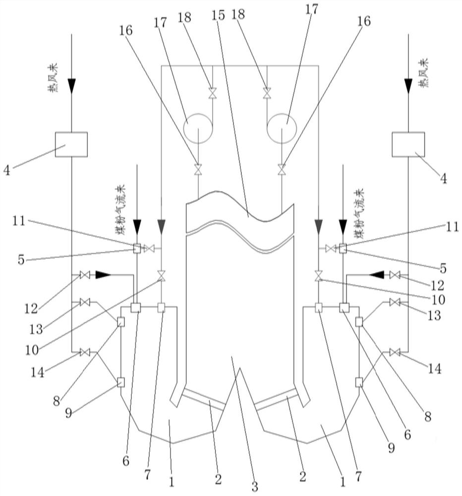
The invention belongs to the technical field of coal-fired power generation, and discloses a low-nitrogen combustion system and method for a double-U-shaped liquid slagging boiler containing staged furnace smoke. The system comprises a first assembly and a second assembly which are connected with two combustion chambers of the double-U-shaped liquid slagging boiler respectively, and the first assembly and the second assembly both comprise air-pulverized coal combustion systems and furnace smoke systems. Each air-pulverized coal combustion system comprises a hot air pipeline, a pulverized coalcombustor and a pulverized coal pipeline. Each furnace smoke system comprises a furnace smoke nozzle, a furnace smoke pipeline and a furnace smoke fan. One end of each furnace smoke pipeline is connected with an outlet of the corresponding furnace smoke fan, and a first furnace smoke branch and a second furnace smoke branch are arranged at the other end of each furnace smoke pipeline. The first furnace smoke branches are connected with the pulverized coal pipelines, the second furnace smoke branches are connected with the combustion chambers of the double-U-shaped liquid slagging boiler by connecting the furnace smoke nozzles, and inlets of the furnace smoke fans are connected with the double-U-shaped liquid slagging boiler. The extracted furnace smoke is divided into two stages and is fedinto the combustion chambers from the pulverized coal combustor nozzles of the pulverized coal pipelines and independent furnace smoke nozzles, so that the amount of NOx generated by combustion is effectively reduced.

Description

technical field [0001] The invention belongs to the technical field of coal-fired power generation, and relates to a low-nitrogen combustion system and method for a double U-shaped liquid slagging boiler containing classified furnace smoke. Background technique [0002] The low-nitrogen combustion of the double U-shaped liquid slagging boiler is limited by the small size of the boiler, and the "U"-shaped combustion method is adopted. The combustion process in the furnace is carried out under high temperature and high environment to facilitate the formation of liquid slagging, which is different from the common The low-nitrogen combustion of tangential and hedging boilers requires combustion under low-temperature and low-oxygen conditions, which is contrary to the control requirements for low NOx formation. [0003] Therefore, the amount of NOx generated at the furnace outlet of the current double U-shaped liquid slagging boiler is generally high, which is very unfavorable fo...

Claims


Application Information

Patent Timeline
Patent Type & Authority Applications(China)
IPC IPC(8): F23C9/06F23N1/06
CPCF23C9/06F23N1/062
Inventor 汪华剑马翔邓玲恵白鹏王洋房凡吴庆龙陈煜严响林周虹光
Owner XIAN THERMAL POWER RES INST CO LTD
Why Eureka
Try Eureka