
Full-speed-domain sensorless composite control system and method for permanent magnet synchronous motor

A permanent magnet synchronous motor, composite control technology, applied in control system, motor control, vector control system and other directions, can solve the problem of difficult to extract useful signal rotor position information, relying on fundamental wave excitation signal, single and other problems

Pending Publication Date: 2021-02-05
NANJING UNIV OF INFORMATION SCI & TECH
View PDF0 Cites 4 Cited by
  • Summary
  • Abstract
  • Description
  • Claims
  • Application Information

AI Technical Summary

Problems solved by technology

[0006] When the permanent magnet synchronous motor runs in the zero-low speed range, the counter electromotive force is very small or even zero, and it is not easy to extract useful signals to estimate the rotor position information. The sensorless control method commonly used in medium and high speeds is not suitable for permanent magnet synchronous motors Running at zero speed and low speed
The sensorless control of permanent magnet synchronous motors in the medium and high speed domain is mostly based on the motor model. According to the relationship between the back electromotive force and the electrical angle, the speed is estimated by extracting the signal related to the speed in the fundamental wave excitation model of the motor. There is no need to use the salient pole effect of the motor, but these methods rely too much on the fundamental wave excitation signal, so that such methods cannot guarantee the detection accuracy of the rotor speed and position when the motor is running at low speed
[0007] Therefore, there is no single sensorless control method that can accurately estimate the rotor position and speed information of permanent magnet synchronous motors in the full speed range.

Method used


Image

  • Full-speed-domain sensorless composite control system and method for permanent magnet synchronous motor
  • Full-speed-domain sensorless composite control system and method for permanent magnet synchronous motor
  • Full-speed-domain sensorless composite control system and method for permanent magnet synchronous motor

Examples


Embodiment 1

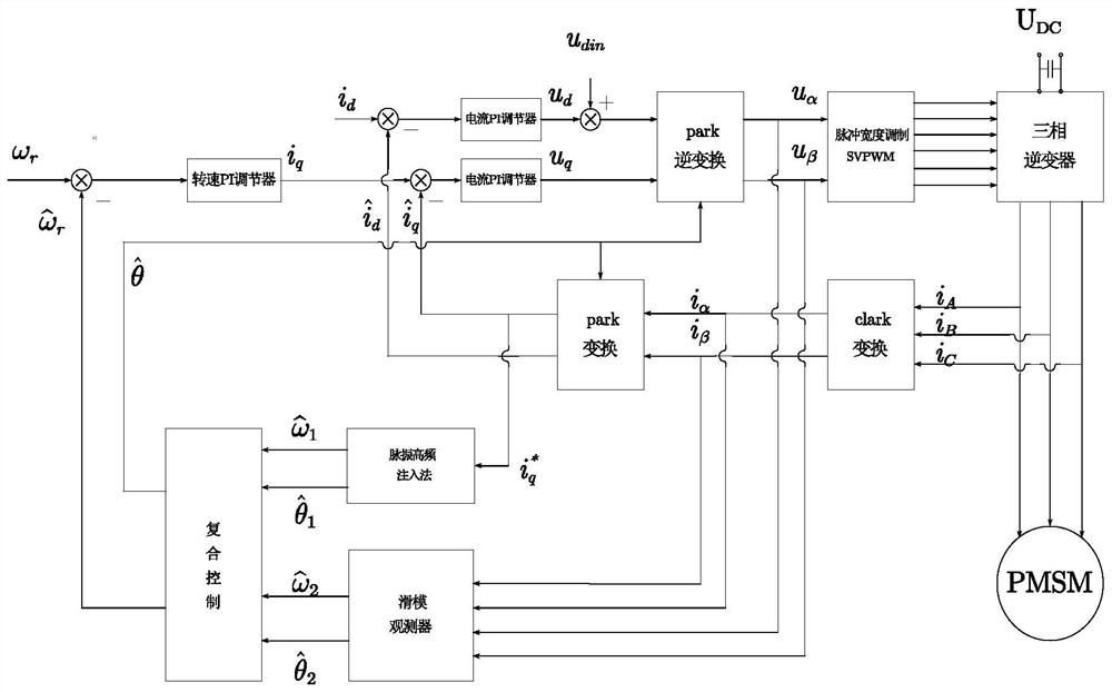
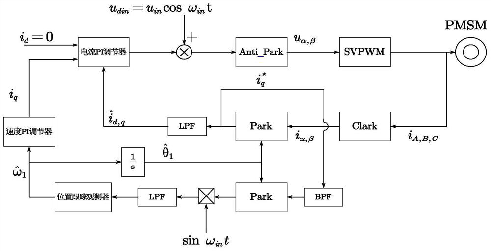
[0076] Such as figure 1 As shown, a structural block diagram of a full-speed sensorless composite control system and control method for a permanent magnet synchronous motor in this embodiment includes: a rotational speed PI regulator, a current PI regulator, a first comparator, a second comparator, The third comparator, the fourth comparator, the Clark transformation module, the Park transformation module, the pulse width modulation module, the three-phase inverter module, the Park inverse transformation module, the sliding mode observer module, the pulse vibration high-frequency voltage injection method module, Composite control module.

[0077] The specific connection of each module is as follows: the input end of the Clark transformation module is connected to the output end of the three-phase stator current of the permanent magnet synchronous motor, and the output end is respectively connected to the input end of the Park transformation module and the two-phase current inp...


PUM


Abstract

The invention discloses a full-speed-domain sensorless composite control system and method for a permanent magnet synchronous motor, and the system employs a sensorless technology to replace a conventional mechanical sensor, detects the position and rotating speed of a rotor of the permanent magnet synchronous motor, simplifies the structure, and improves the reliability. According to the presentinvention, by combining a pulse vibration high-frequency voltage injection method suitable for a zero-low speed range with a sliding mode observer method suitable for a medium-high speed range are combined, the disturbance problem of a conventional single sensorless control method in different speed ranges is solved, and the operation of the sensorless control system of the permanent magnet synchronous motor in the full-speed-domain range is achieved.

Description

Technical field: [0001] The invention belongs to the technical field of permanent magnet motor control, and in particular relates to a sensorless composite control system and control method in the full speed range of a permanent magnet synchronous motor. Background technique: [0002] It has been nearly 200 years since the world's first electric motor came out. As an important electromechanical equipment supporting people's production and life, its development and improvement have attracted people's attention. In the past ten years, with the development of NdFeB permanent magnet material technology with low price, high magnetic energy product and high coercive force, the permanent magnet synchronous motor (Permanent Magnet Synchronous Motor, PMSM) has a simple structure, high power density, With the characteristics of small moment of inertia, fast dynamic response and high efficiency and energy saving, it has been widely used in many fields such as household appliances, ind...

Claims


Application Information

Patent Timeline
IPC IPC(8): H02P6/18H02P6/182H02P6/34H02P21/00H02P21/13H02P21/18H02P21/22H02P21/24H02P25/024H02P27/08
CPCH02P6/183H02P6/182H02P6/34H02P21/0007H02P21/13H02P21/18H02P21/22H02P21/24H02P25/024H02P27/08H02P2203/11H02P2203/05H02P2203/09H02P2207/05
Inventor 李伯涵余莉
Owner NANJING UNIV OF INFORMATION SCI & TECH
Learn More