A CNC machine tool with automatic chip removal function

A technology of CNC machine tools and chip removal machines, which is applied in the direction of manufacturing tools, metal processing machinery parts, metal processing equipment, etc., can solve problems such as cleaning difficulties, iron filings splashing around, and affecting the efficiency of workpiece processing, so as to reduce soil acidity, Easy to clean and prevent rust and corrosion

Active Publication Date: 2022-04-22
温岭市箬横仪表机械配件厂
View PDF8 Cites 0 Cited by
  • Summary
  • Abstract
  • Description
  • Claims
  • Application Information

AI Technical Summary

Problems solved by technology

[0005] The object of the present invention is to provide a kind of numerically controlled machine tool with automatic chip removal function, to solve the problem that the existing numerically controlled machine tool in the above background technology is processing the workpiece by the rapid rotation of the tool when the workpiece is processed, so when processing the workpiece The generated iron filings will splash around, making the working room dirty and difficult to clean; at the same time, when the CNC machine tool is processing the workpiece, in order to prevent the surface temperature of the processed workpiece from being too high, it will use coolant to cool the workpiece Therefore, after the processing is completed, a large amount of water vapor will remain in the working room of the CNC machine tool. If it is not handled in time, it will cause rusting of the processed parts in the working room, thereby affecting the efficiency of workpiece processing; in addition, after the chuck is fixed to the tool , the workpiece needs to be processed by rotation, but when the rotating chuck fails, the high-speed rotating chuck may drop the tool, which may cause a safety accident

Method used


Image

  • A CNC machine tool with automatic chip removal function
  • A CNC machine tool with automatic chip removal function
  • A CNC machine tool with automatic chip removal function

Examples


Embodiment 1

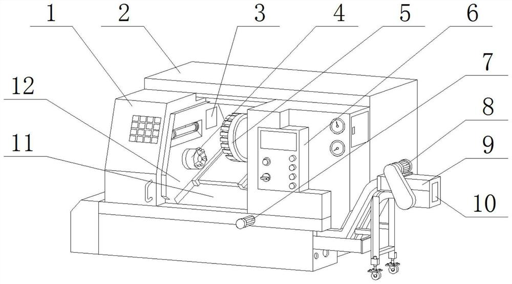
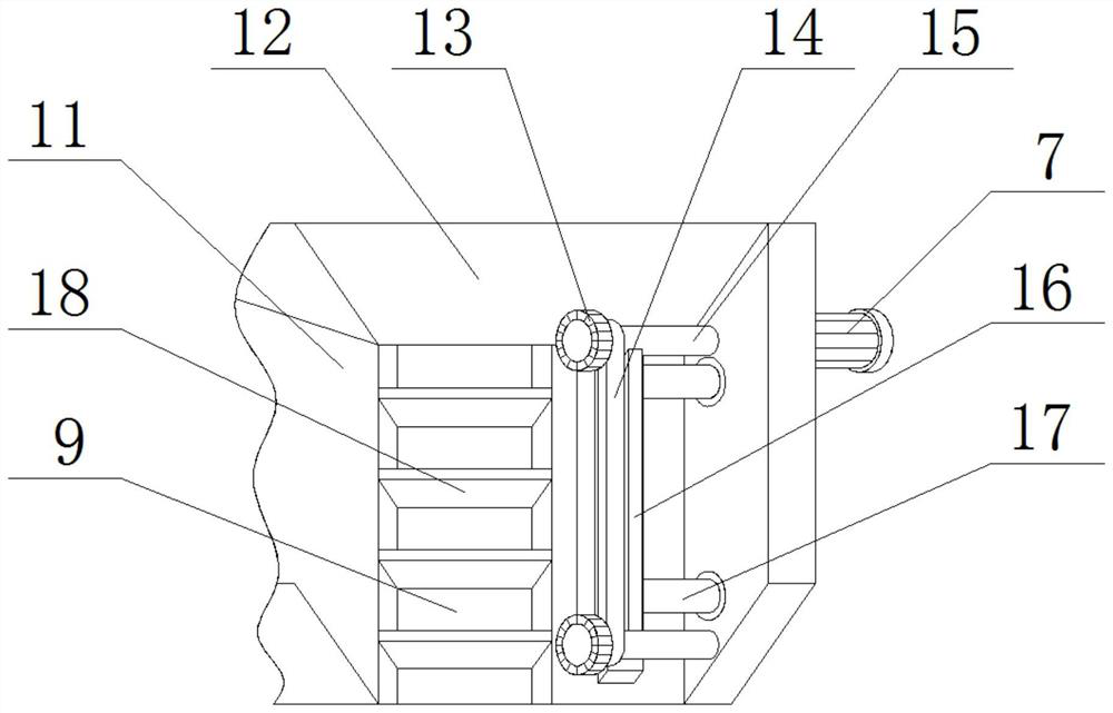
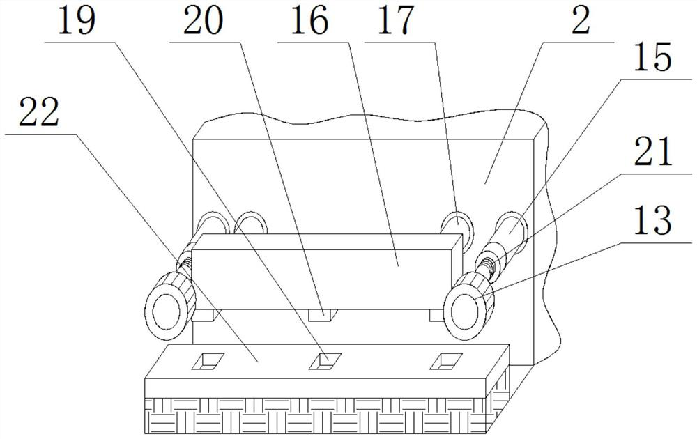
[0030] see Figure 1-Figure 3, the present invention provides a CNC machine tool with automatic chip removal function; comprising a CNC machine tool shell 2, a working room 12 is provided at the inner middle position of the CNC machine tool shell 2, and an absorption box 3 is movably installed above the left end of the working room 12 , a chuck 4 is fixedly installed under the left end of the working room 12, a chip plate 11 is welded and installed under the right side of the chuck 4, a fixed disk 5 is movably installed at the right end of the working room 12, and the left side of the front surface of the outer shell of the CNC machine tool 2 A numerically controlled machine tool door cover 1 is installed movable, a control box 6 is fixedly installed on the right side of the front surface of the numerically controlled machine tool shell body 2, a first motor 7 is fixedly mounted below the control box 6, and a row The chip machine shell 9, the second motor 8 is fixedly installe...

Embodiment 2

[0034] see Figure 4 , the stirring blades 25 are provided with several groups, and several groups of stirring blades 25 are uniformly welded and fixed on the outer surface of the rotating shaft 24, the rotating shaft 24 and the absorption box 3 are connected through the rotating shaft rotation, and the rotating shaft 24 is driven by a motor to rotate at a low speed; The storage port 23 is opened on the outer casing 2 of the CNC machine tool inside the working room 12. Two groups of sliders 26 and chutes 28 are respectively arranged. The two groups of sliders 26 are welded and fixed on the left and right sides of the absorption box 3 respectively. 28 are respectively fixed on the left and right sides of the inner surface of the storage opening 23 by screws, and the handle 27 and the absorption box 3 are fixedly connected by screws.

[0035] In this embodiment, the absorption box 3 that can slide in the storage port 23 is provided, and the rotation shaft 24 rotated by the motor...

Embodiment 3

[0037] see Figure 5 and Figure 6 , the mounting hole 33 is provided inside the left end of the chuck 4, the limit block 29, the fixing hole 36 and the spring 37 are respectively provided with four groups, and the four groups of fixing holes 36 are evenly opened in the inside of the rotating disk 30, and one end of the four groups of springs 37 is welded Be fixed on the bottom of four groups of fixing holes 36, the other end of four groups of springs 37 is welded and fixed on the bottom of four groups of limiting blocks 29, and four groups of limiting blocks 29 are all placed in the inside of four groups of fixing holes 36; The main shafts 35 are fixedly connected by screws, and there are several groups of mounting holes 33, and several groups of mounting holes 33 are evenly opened on the chuck 4 and the rotating disk 30, so that the screws can be fixed in the mounting holes 33, so that the chuck 4 is fixed on the On the turntable 30, a first limiting hole 34 is provided at ...


PUM


Abstract

The invention discloses a numerically controlled machine tool with automatic chip removal function, which comprises an outer body of the numerically controlled machine tool, a working chamber is provided at the middle position inside the outer body of the numerically controlled machine tool, and an absorbing box is movably installed above the left end of the working room. A chuck is fixedly installed under the left end of the working room; this program designs a free telescopic telescopic rod and a second cleaning brush that is engaged and fixed on the support rod, and rotates the first cleaning brush through a belt, so as to facilitate the cleaning of the working room. At the same time, the calcium oxide in the absorption box can fully absorb and react with the residual moisture in the working room after the processing is completed by setting up a sliding absorption box and a low-speed rotating stirring blade in the absorption box. Prevent rust and corrosion of the parts in the working chamber, and set a limit block that will pop out when the high-speed rotation is exceeded, so that the chuck can reduce the speed and be stuck, thereby ensuring the safety of use.

Description

technical field [0001] The invention belongs to the technical field of numerical control machine tools, and in particular relates to a numerical control machine tool with automatic chip removal function. Background technique [0002] A CNC machine tool is an automatic machine tool equipped with a program control system; the control system can logically process the program specified by the control code or other symbolic instructions, decode it, express it in coded numbers, and input it into the CNC machine tool through the information carrier. Device; After calculation and processing, various control signals are sent by the numerical control device to control the movement of the machine tool, and automatically process the parts according to the shape and size required by the drawing. [0003] Existing CNC machine tools still have some deficiencies during use. For example, when the existing CNC machine tools are processing workpieces, the workpieces are processed by the rapid ...

Claims


Application Information

Patent Timeline
Patent Type & Authority Patents(China)
IPC IPC(8): B23Q11/00B23B31/02
CPCB23Q11/0042B23Q11/00B23B31/02
Inventor 何健君
Owner 温岭市箬横仪表机械配件厂
Why Eureka
Try Eureka