Biomass direct liquefaction reactor, reactor system and biomass direct liquefaction method

A reactor system and reactor technology, which are used in the preparation of liquid hydrocarbon mixtures, the petroleum industry, and the treatment of hydrocarbon oils, can solve problems such as difficult separation and complex components, and achieve reduced gas-liquid ratio, low product oxygen content, Beneficial for deep deoxidation

Active Publication Date: 2021-02-26
山东汇邦新材料有限公司
View PDF4 Cites 0 Cited by
  • Summary
  • Abstract
  • Description
  • Claims
  • Application Information

AI Technical Summary

Problems solved by technology

[0004] Due to the high oxygen content and complex components, the liquefied oil contains a large amount of oxygen-containing compounds such as alcohols, lipids, aldehydes, and carboxylic acids. During the subsequent product separation process, these oxygen-containing compounds are very easy to form co- Boilers or emulsions, difficult to separate

Method used


Image

  • Biomass direct liquefaction reactor, reactor system and biomass direct liquefaction method
  • Biomass direct liquefaction reactor, reactor system and biomass direct liquefaction method

Examples


Embodiment 1

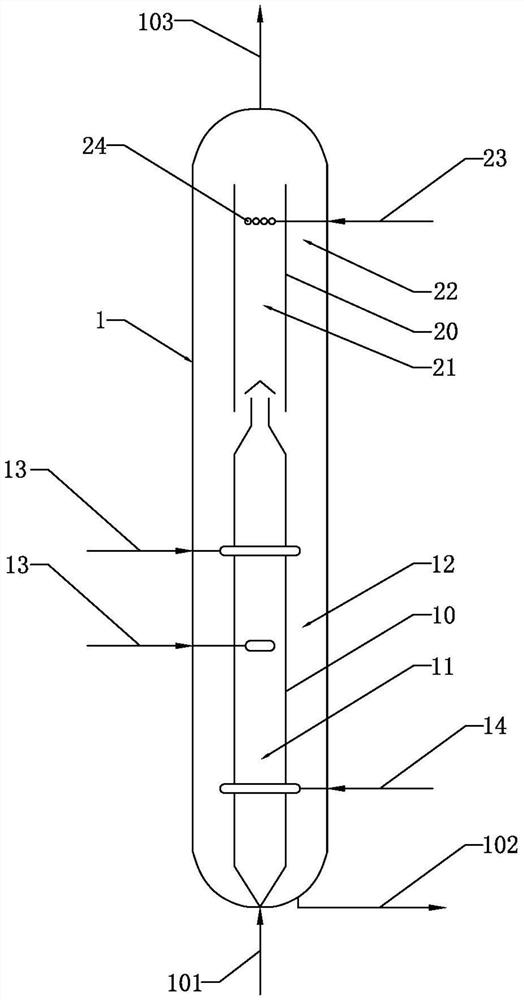
[0037] See figure 1 , a biomass direct liquefaction reactor, the liquefaction reactor includes a reactor shell 1 and a reaction zone and a separation zone arranged in the reactor shell 1, the reaction zone is located in the lower part of the reactor shell 1, separated The zone is located in the upper part of the reactor shell 1, the bottom of the reactor shell 1 is provided with a raw material inlet 101 and a first product outlet 102, and the top of the reactor shell is provided with a second product outlet 103;

[0038] The reaction zone is divided into a primary reaction zone 11 and a secondary reaction zone 12 by the first built-in sleeve 10, and the primary reaction zone 11 located in the first built-in sleeve 10 is the primary reaction zone 11 under the syngas atmosphere, where the liquefaction reaction of biomass takes place; The secondary reaction zone 12 is located between the first built-in sleeve 10 and the reactor shell 1, and performs a hydrodeoxygenation reaction ...

Embodiment 2

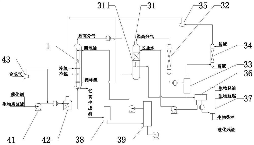
[0043] See figure 2 , a biomass direct liquefaction reactor system, the reactor system includes the above-mentioned liquefaction reactor.

[0044] In this embodiment, the reactor system also includes a raw material delivery unit, the raw material delivery unit includes a booster pump 41, a new hydrogen compressor 42 and a heating furnace 43, and the inlets of the booster pump 41 are respectively connected to the biomass slurry delivery pipe , the catalyst delivery pipe, the inlet of the new hydrogen compressor 42 is connected to the synthesis gas delivery pipe, the inlet of the heating furnace 43 is connected with the outlet of the booster pump 41 and the outlet of the new hydrogen compressor 42 respectively, and the outlet of the heating furnace 43 is connected with the liquefaction reactor The raw material inlet 101 is connected.

[0045] In this embodiment, the reactor system further includes a product separation unit, and the product separation unit includes a warm and h...

Embodiment 3

[0049] A biomass direct liquefaction method based on the reactor system described above. The biomass slurry and the catalyst are boosted by a pump, mixed and heated with the boosted syngas, and then enter the raw material inlet of the liquefaction reactor, in the primary reaction zone 11 After the liquefaction reaction is completed, the gas phase enters the primary reaction oil-gas separation zone 21, and the liquid phase enters the secondary reaction zone 12 for further hydrodeoxygenation reaction;

[0050] After the primary reaction oil and gas are in countercurrent contact with the low-temperature re-refined oil in the primary reaction oil-gas separation zone 21, the high-boiling point oxygen-containing compounds are condensed, and the uncondensed oil and gas are mixed with the oil and gas in the secondary reaction oil-gas separation zone 22. The second product outlet 103 of the device is derived.

[0051] The reaction oil gas derived from the second product outlet 103 of t...


PUM


Abstract

The invention relates to the technical field of petrochemical engineering, in particular to a biomass direct liquefaction reactor, a reactor system and a biomass direct liquefaction method. Biomass slurry and a catalyst are pressurized by a pump, mixed and heated with pressurized synthesis gas, then enter a lower inlet of the liquefaction reactor, and are subjected to liquefaction reaction in a primary reaction zone, the gas phase enters a primary reaction oil-gas separation zone, and the liquid phase enters a secondary reaction zone for further hydrodeoxygenation reaction. The primary reaction zone and the secondary reaction zone are connected in series, and the primary reaction zone adopts a gas-liquid cocurrent flow up-flow reactor structure, so that the back-mixing strength is high, and heat transfer in the liquefaction reaction process is facilitated; the secondary reaction zone adopts a gas-liquid reverse-flow type slurry bed reactor structure, and meanwhile, the gas-liquid ratiois reduced, the gas chlorine content is reduced, the back-mixing degree of generated oil is properly reduced, the retention time of liquid is prolonged, and deep deoxidation of the liquefied generated oil is facilitated.

Description

technical field [0001] The invention relates to the technical field of petrochemical industry, in particular to a biomass direct liquefaction reactor, a reactor system and a biomass direct liquefaction method. Background technique [0002] The oxygen content of biomass is as high as 40%, and the direct liquefaction reaction of biomass is mainly deoxidation reaction, and the oxygen content of the liquid product obtained under CO atmosphere is lower than that of H 2 Oxygen content of the liquid product under atmosphere. The calorific value of the liquid product obtained under CO atmosphere is higher than that of H 2 Calorific value of liquid product under atmosphere. The reaction atmosphere of CO gas, such as synthesis gas, can save the powder drying and hydrogen production process, greatly reduce the processing cost and improve the quality of oil products. [0003] The oxygen content in the liquefied oil is about 10%, which needs to be further reduced through hydrodeoxygen...

Claims


Application Information

Patent Timeline
Patent Type & Authority Applications(China)
IPC IPC(8): C10G1/06C10G1/00
CPCC10G1/065C10G1/002C10G1/008C10G2300/1011
Inventor 郑志斌李奇周喆
Owner 山东汇邦新材料有限公司
Why Eureka
Try Eureka