
Laminar fermentation device and fermentation method thereof

A fermentation device and fermentation tank technology, which is applied in biochemical cleaning devices, biochemical equipment and methods, enzymology/microbiology devices, etc., can solve the problems of small processing capacity, substandard, inconsistent product quality, etc. The effect of pollution

Pending Publication Date: 2021-02-26
王天浩 +1
View PDF0 Cites 2 Cited by
  • Summary
  • Abstract
  • Description
  • Claims
  • Application Information

AI Technical Summary

Problems solved by technology

[0009] 3. The central part of the product quality is good, but the surrounding area is unqualified, and the qualified rate is less than 30%;
[0011] 5. Product quality cannot be tested because it is not up to standard;
[0012] 6. Mixing and exhaust have secondary pollution
[0016] 3. Due to the different process and time of fermentation materials, the quality of the whole product is inconsistent, and less than 1 / 3 of the materials that completely complete the whole process
[0018] 1. The processing capacity is small, and the drum and the central shaft have limited manufacturing limits, so the device is only suitable for small-scale production. Due to the limited length, the material is processed in it for a short time and cannot reach sufficient time for biological reaction;
[0019] 2. The equipment is mainly turned over and thrown, so almost all of it is aerobic fermentation process, resulting in incomplete and insufficient biological treatment of materials;
[0020] 3. Due to the short processing time, it is necessary to assist an external steam boiler to send steam, and the operating cost is relatively high

Method used


Image

  • Laminar fermentation device and fermentation method thereof
  • Laminar fermentation device and fermentation method thereof

Examples


Embodiment Construction

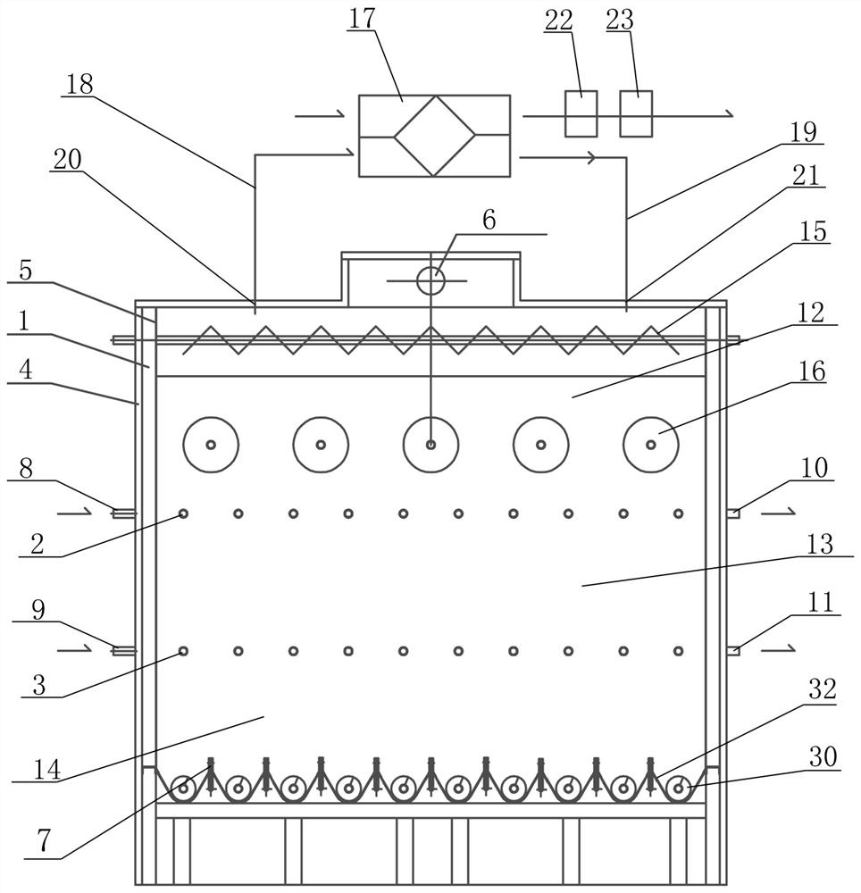
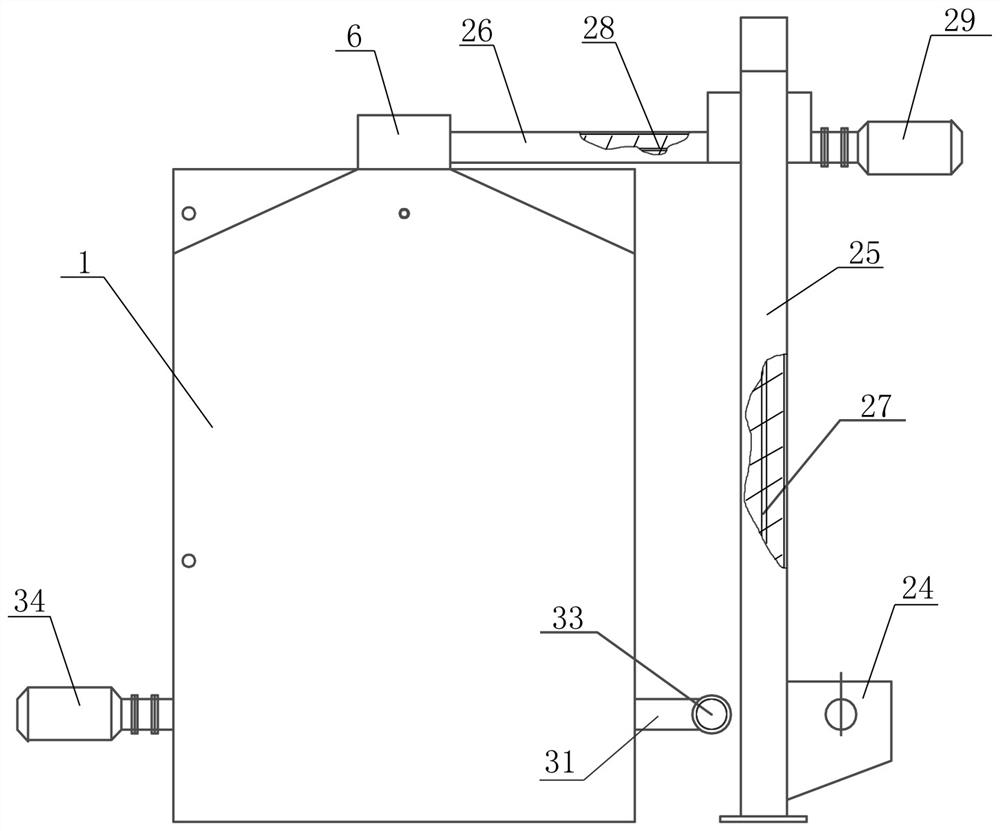
[0050]A laminar flow fermentation device, characterized in that the device includes a fermentation tank 1, a stirring mechanism in the tank, a heat recovery and aeration device, a feeding mechanism, a discharging mechanism, a heating water pipe 2 and a cooling water pipe 3, and the fermentation tank 1 is outside the tank. The end face is fixedly provided with a thermal insulation composite plate 4, and the inner end face is fixedly provided with a stainless steel plate 5. The upper cover of the fermentor 1 is provided with a feed inlet 6, and a plurality of nitrogen input pipes 7 that are passed into the fermentor 1 are provided at the bottom of the fermentor 1. A hot water inlet 8 and a cold water inlet 9 are respectively provided on the side wall of one end of the fermenter 1, and a hot water outlet 10 and a cold water outlet 11 are respectively provided on the side wall of the other end of the fermentation tank 1. The heating water pipe 2 and the cooling water pipe 3 are respecti...


PUM


Abstract

A laminar flow fermentation device is characterized by comprising a fermentation tank, an in-tank stirring mechanism, a heat recovery and air exchange device, a feeding mechanism, a discharging mechanism, a heating water pipe and a cooling water pipe, and the heating water pipe and the cooling water pipe are respectively coiled in the fermentation tank which is divided into three equal sections, namely an aerobic fermentation section, a facultative fermentation section and an anaerobic fermentation section. The in-tank stirring mechanism comprises a plurality of material homogenizing stirringcages and a plurality of turning stirring cages and a heat recovery air interchanger comprises a heat recovery air interchanger, an exhaust pipe and an air inlet pipe and a feeding mechanism comprisesa feeding funnel, a vertical conveying pipe and a transverse conveying pipe, and the discharging mechanism comprises a plurality of laminar flow discharging stirring cages and an external conveying pipe. The fermentation property and the sufficient fermentation environment meet the necessary conditions for completing complete fermentation, materials in the bin move at the same time from top to bottom, the top of the bin is filled with the same amount of materials as discharged materials, and the dynamic full-bin state in the bin is guaranteed all the time.

Description

Technical field[0001]The invention relates to the field of organic waste treatment, in particular to a laminar flow fermentation device and a fermentation method for treating poultry and livestock manure, industrial and agricultural residues, animal and plant wastes.Background technique[0002]With the development of industrial and agricultural economy, in the current process of production and life, especially the development of rural aquaculture, a large amount of animal and plant wastes and production residues, such as poultry manure, wine residue, bean dregs, straw, etc., are generated. These organic substances are Good renewable resources can be processed and utilized to make valuable products. At the same time, if they cannot be processed well, it will cause pollution and harm to people and the environment. At present, most of its biological treatment methods are centralized static treatment methods, that is, a fixed amount of treatment is processed at a time, and each treatment ...

Claims


Application Information

Patent Timeline
IPC IPC(8): C12M1/00C12M1/08C12M1/04C12M1/02
CPCC12M23/02C12M23/34C12M27/06C12M29/06C12M33/16C12M41/12C12M41/24
Inventor 王斌
Owner 王天浩
Learn More