Target cooling back plate and preparation method thereof
A target and backplane technology, applied in the field of magnetron sputtering, can solve the problems of low reuse rate of cooling backplane, high cost of cooling backplane, water leakage of flange joints and cooling backplane, etc., to improve reuse efficiency, prevent leakage problems, and increase the number of times consumed
- Summary
- Abstract
- Description
- Claims
- Application Information
AI Technical Summary
Problems solved by technology
Method used
Image
Examples
Embodiment 1
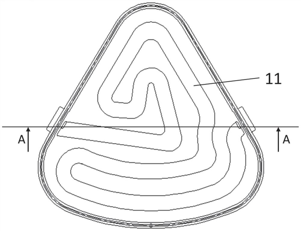
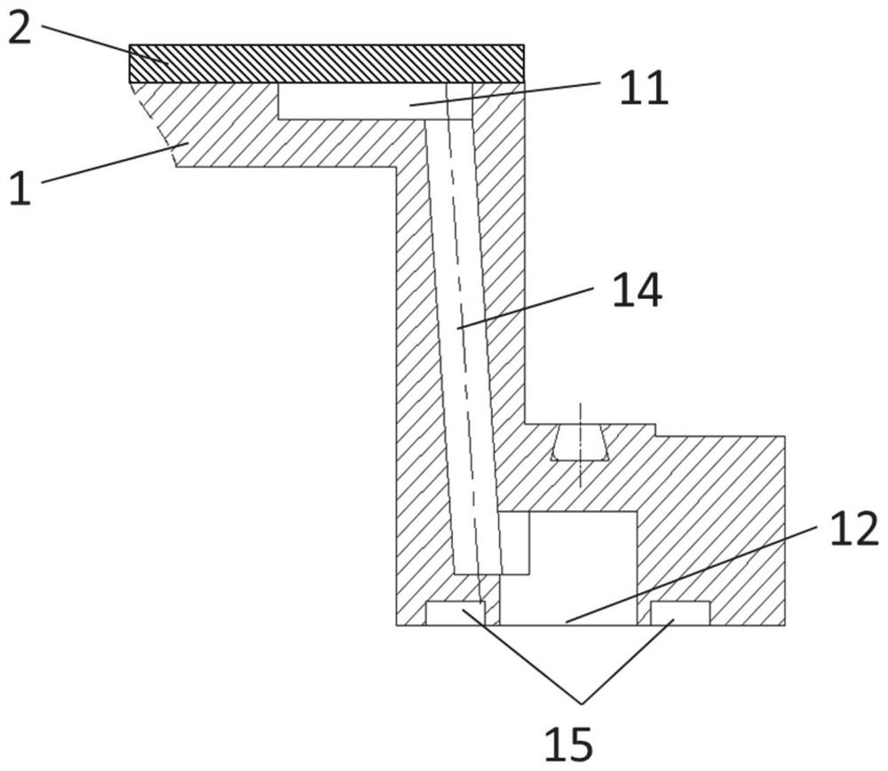
[0058] This embodiment provides a target cooling back plate and a preparation method thereof, such as Figure 1-4 As shown, the target cooling back plate includes a base 1 and a cover plate 2, the base 1 includes a cooling water channel 11, a water inlet 12 and a water outlet 13, and the water inlet 12 and the water outlet 13 are opened in the On the bottom surface of the base 1 , inclined water passages 14 are opened between the cooling water passage 11 , the water inlet 12 and the water outlet 13 respectively. The base 1 is connected to the water inlet 12 and the water outlet. Flange connection holes 15 are respectively opened around 13;
[0059] The thickness of the cover plate 2 is 4.5 mm, the width of the cooling water channel 11 is 30 mm, and the depth is 8 mm, a sandblasting layer is provided on the inner surface of the cooling water channel 11, and the target material cools the outside of the back plate The shape is a triangle.
[0060] The preparation method compris...
Embodiment 2
[0066] This embodiment provides a target cooling backplane and a preparation method thereof. The target cooling backplane includes a base 1 and a cover plate 2 , and the base 1 includes a cooling water channel 11 and a water inlet 12 and a water outlet 13 . , the water inlet 12 and the water outlet 13 are opened on the bottom surface of the base 1, the cooling water channel 11 and the water inlet 12 and the water outlet 13 are respectively opened with inclined water channels 14, the The base 1 is provided with flange connection holes 15 around the water inlet 12 and the water outlet 13 respectively;
[0067] Wherein, the thickness of the cover plate 2 is 5 mm, the width of the cooling water channel 11 is 50 mm, and the depth is 12 mm, a sandblasting layer is arranged on the inner surface of the cooling water channel 11, and the external shape of the target cooling back plate is is circular.
[0068] The preparation method comprises the following steps:
[0069] (1) machining...
Embodiment 3
[0074] This embodiment provides a target cooling backplane and a preparation method thereof. The target cooling backplane includes a base 1 and a cover plate 2 , and the base 1 includes a cooling water channel 11 and a water inlet 12 and a water outlet 13 . , the water inlet 12 and the water outlet 13 are opened on the bottom surface of the base 1, the cooling water channel 11 and the water inlet 12 and the water outlet 13 are respectively opened with inclined water channels 14, the The base 1 is provided with flange connection holes 15 around the water inlet 12 and the water outlet 13 respectively;
[0075] The thickness of the cover plate 2 is 4.8 mm, the width of the cooling water channel 11 is 40 mm, and the depth is 10 mm, a sandblasting layer is provided on the inner surface of the cooling water channel 11, and the target material cools the outside of the back plate The shape is a triangle.
[0076] The preparation method comprises the following steps:
[0077] (1) mac...
PUM
| Property | Measurement | Unit |
|---|---|---|
| diameter | aaaaa | aaaaa |
| height | aaaaa | aaaaa |
| surface roughness | aaaaa | aaaaa |
Abstract
Description
Claims
Application Information
 - R&D
- Intellectual Property
- Life Sciences
- Materials
- Tech Scout
- Unparalleled Data Quality
- Higher Quality Content
- 60% Fewer Hallucinations
Browse by: Latest US Patents, China's latest patents, Technical Efficacy Thesaurus, Application Domain, Technology Topic, Popular Technical Reports.
© 2025 PatSnap. All rights reserved.Legal|Privacy policy|Modern Slavery Act Transparency Statement|Sitemap|About US| Contact US: help@patsnap.com


