
Synchronous rectification device and control method thereof

A technology of synchronous rectification and control method, applied in the direction of circuit devices, battery circuit devices, output power conversion devices, etc., can solve the problems of switching power supply efficiency reduction, loss, loss increase, etc., to reduce heat generation and standby power consumption, The effect of small current consumption and long intermittent time

Pending Publication Date: 2021-02-26
MORNSUN GUANGZHOU SCI & TECH
View PDF2 Cites 1 Cited by
  • Summary
  • Abstract
  • Description
  • Claims
  • Application Information

AI Technical Summary

Problems solved by technology

[0002] A diode is a commonly used rectifying device. It is turned on when a forward voltage is applied, and the current flows forward, while it is turned off when a reverse voltage is applied, and the reverse current is blocked. Because the diode has an inherent conduction when it is turned on The greater the current, the greater the voltage drop. The loss of a diode is usually described as the current multiplied by the conduction voltage drop. Therefore, as the current flowing through the diode increases, its loss also increases. Causes a reduction in switching power supply efficiency
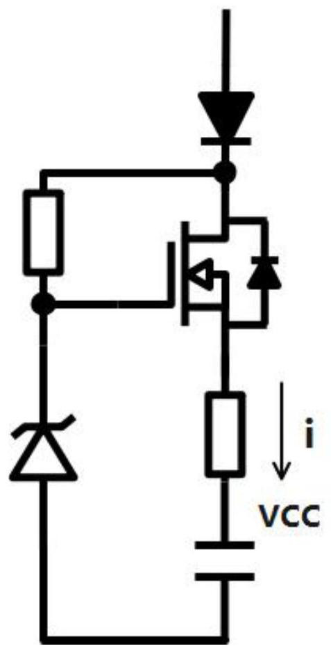
The schematic diagram of the charging circuit is shown in figure 1 As shown, including charging MOS tubes, voltage regulator tubes, etc., the basic principle is to use the reverse voltage generated by the secondary side rectifier to supply power to the control circuit through the switching action of the primary side of the isolation topology, and the voltage regulator tube connected to the gate of the charging MOS tube Clamp the Vcc voltage. During normal operation, when the difference between the Vcc voltage and the gate voltage of the charging MOS tube is less than the turn-on threshold of the auxiliary transistor, stop charging Vcc, so the Vcc voltage is clamped to a certain voltage value by the voltage regulator tube. In practical applications, when the circuit reaches a steady state, the auxiliary transistor works in a non-completely conducting state, similar to a linear regulator, and there will be current flowing through the auxiliary transistor in each cycle, resulting in a huge power loss, resulting in Problems of heat generation, low efficiency and large standby power consumption

Method used


Image

  • Synchronous rectification device and control method thereof
  • Synchronous rectification device and control method thereof
  • Synchronous rectification device and control method thereof

Examples


specific Embodiment

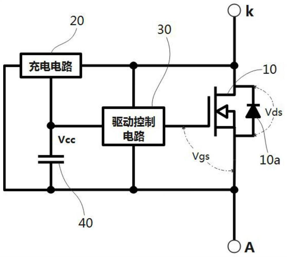
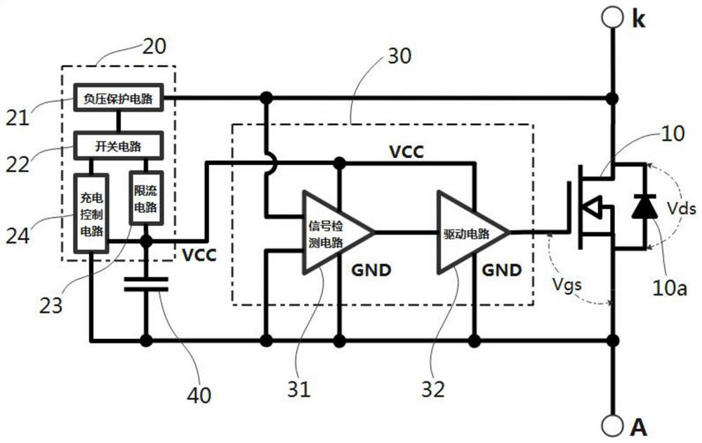
[0025] Such as figure 2 Shown is a schematic structural diagram of a synchronous rectification device of the present invention, including a synchronous rectifier tube 10 , a charging circuit 20 , a drive control circuit 30 and a Vcc capacitor 40 . The synchronous rectifier 10 is an N-channel MOS transistor with three terminals, the three terminals are the drain, the source and the gate respectively, the voltage between the gate and the source is represented as the driving voltage Vgs, and the drain is represented as The cathode K of the synchronous rectification device has its source as the anode A of the synchronous rectification device, and a diode 10a is connected between the anode A and the cathode K; the input terminal of the charging circuit 20 is connected to the cathode K of the synchronous rectification device and the drive control circuit 30 The first input end of the charging circuit 20 is connected to one end of the Vcc capacitor 40 and the second input end of the...


PUM


Abstract

A synchronous rectification device comprises a synchronous rectification tube, a drive control circuit, a Vcc capacitor and a charging circuit for charging a grid electrode of the synchronous rectification tube. The Vcc capacitor is charged through the charging circuit by means of reverse voltage applied to the synchronous rectification device, and when the voltage of the Vcc capacitor is detectedto rise to the upper limit value Vcc_H of the Vcc capacitor, charging of the Vcc capacitor is stopped; and when the Vcc voltage is detected to be reduced to a lower limit value Vcc L, starting to charge the Vcc capacitor is carried out, so that a switching tube of the charging circuit works in an intermittent and complete conduction state. By controlling the upper limit and the lower limit of theVcc voltage, the charging circuit is promoted to work intermittently, and the power consumption of the power supply circuit is greatly reduced; in a standby state, when the working frequency is lower, the current consumption of the Vcc end is extremely low, the working intermittent time of the charging circuit is longer, the power consumption is further reduced, and the heating and standby powerconsumption is reduced.

Description

technical field [0001] The invention relates to the technical field of switching power supplies, in particular to a power supply technology of a synchronous rectification device and a control method thereof. Background technique [0002] A diode is a commonly used rectifying device. It is turned on when a forward voltage is applied, and the current flows forward, while it is turned off when a reverse voltage is applied, and the reverse current is blocked. Because the diode has an inherent conduction when it is turned on The greater the current, the greater the voltage drop. The loss of a diode is usually described as the current multiplied by the conduction voltage drop. Therefore, as the current flowing through the diode increases, its loss also increases. Resulting in a reduction in switching power supply efficiency. In order to solve the problem of rectification diode loss, power semiconductor devices, such as MOS tubes, can be used to replace diode rectification, that i...

Claims


Application Information

Patent Timeline
Patent Type & Authority Applications(China)
IPC IPC(8): H02M7/217H02J7/06
CPCH02J7/06H02M7/217H02M1/0032H02M1/0054Y02B70/10
Inventor 周瑜薛泽宇
Owner MORNSUN GUANGZHOU SCI & TECH
Learn More