Design method and application of nonlinear diffractive optical element

A diffractive optical element and design method technology, applied in the field of nonlinear photonics, can solve the problems of large design error, complex manufacturing, limited application, etc., and achieve the effect of reducing design error and manufacturing difficulty and high versatility

Active Publication Date: 2021-03-09
HUAZHONG UNIV OF SCI & TECH
View PDF2 Cites 1 Cited by
  • Summary
  • Abstract
  • Description
  • Claims
  • Application Information

AI Technical Summary

Problems solved by technology

[0006] The invention provides a design method of a nonlinear diffractive optical element and its application, which is used to solve the technical problem that the existing design method of a nonlinear diffractive optical element is limited in application due to large design errors and complicated manufacturing

Method used


Image

  • Design method and application of nonlinear diffractive optical element
  • Design method and application of nonlinear diffractive optical element
  • Design method and application of nonlinear diffractive optical element

Examples


Embodiment 1

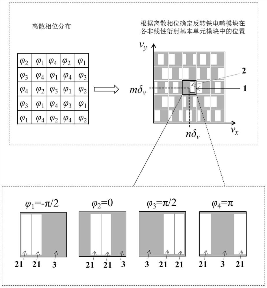
[0038] A design method for nonlinear diffractive optical elements, such as figure 1 shown, including:

[0039] The nonlinear diffractive optical element includes a plurality of nonlinear diffractive basic unit modules 1 arranged in space, and the design process includes the following steps:

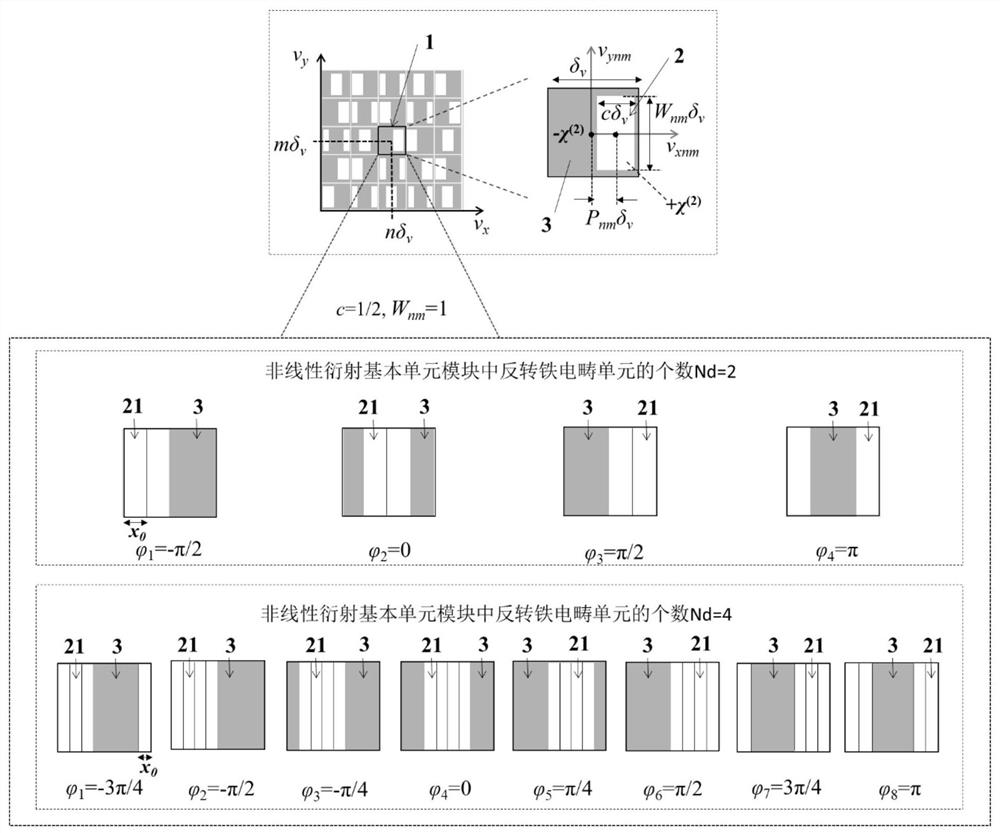
[0040] According to the target second harmonic light field intensity distribution in the far field, the discrete phase distribution at different spatial positions of the holographic plane is determined, and then the nonlinear diffraction basic unit module corresponding to each discrete phase is determined one by one; each nonlinear diffraction The basic unit module 1 includes an inverted ferroelectric domain module 2 and a ferroelectric domain background substrate module 3, and the positional relationship between the inverted ferroelectric domain module and the ferroelectric domain background substrate module in the nonlinear diffraction basic unit module is determined by the discrete pha...

Embodiment 2

[0080] An application of the design method of a nonlinear diffractive optical element as described in Embodiment 1 above for holographic imaging, specifically:

[0081] Determining multiple discrete phases based on the continuous phase distribution on the holographic surface of the target pattern;

[0082] A nonlinear diffractive optical element is designed by using the method for designing a nonlinear diffractive optical element as described in Embodiment 1 above, and is used for holographic imaging of a target pattern.

[0083] The continuous phase of the target light field refers to the continuous phase distribution on the holographic surface, which is obtained from the amplitude of the target light field on the image plane through an iterative Fourier transform algorithm.

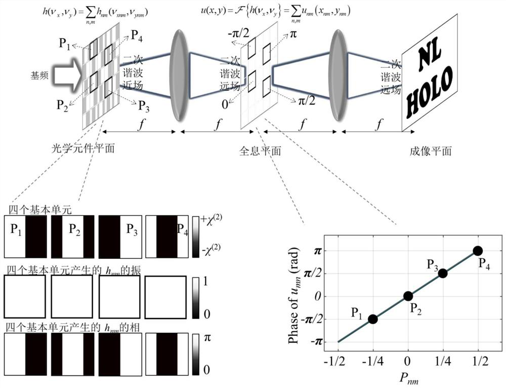
[0084] Such as Figure 4 As shown, it is a schematic diagram of the processing of the nonlinear diffractive optical element corresponding to the H-type SHG holographic imaging. Figure 4 The upper lef...


PUM

PropertyMeasurementUnit
wavelengthaaaaaaaaaa

Abstract

The invention belongs to the field of nonlinear photonics, and particularly relates to a design method and application of a nonlinear diffractive optical element. A nonlinear diffractive optical element comprises a plurality of nonlinear diffraction basic unit modules; according to target second harmonic light field distribution in the far field, discrete phase distribution at different spatial positions of the holographic plane is determined, and then basic unit modules in one-to-one correspondence with the discrete phases are determined; and each basic unit module comprises a reverse ferroelectric domain module and a ferroelectric domain background substrate module, the position of the reverse ferroelectric domain module in the basic unit module is determined through the discrete phase,the value range of the discrete phase is 0-2 [pi], and the nonlinear diffractive optical element is obtained. The arrangement of different basic unit modules at the corresponding spatial positions isdetermined according to the discrete phase values at the different spatial positions, the phase of the generated coherent second harmonic wavefront can be randomly regulated and controlled, and the method has high universality and flexibility, small design error and low manufacturing difficulty.

Description

technical field [0001] The invention belongs to the field of nonlinear photonics, and more specifically relates to a design method of a nonlinear diffractive optical element and its application. Background technique [0002] Second-order nonlinear coefficient (χ (2) ) spatially modulated nonlinear photonic crystals play an important role in the field of second-order nonlinear wavefront shaping and nonlinear holography. spatially modulated χ (2) The microstructure provides a set of reciprocal lattice vectors, which can compensate the phase mismatch between interacting waves during optical frequency conversion, so that energy exchange between these waves can be performed efficiently. This technique is called quasi-phase matching technique. In fact, the nonlinear χ (2) Sign inversion (corresponding to 180-degree inversion of the ferroelectric domain) will bring an additional π phase difference to the nonlinearly polarized wave. Therefore, in the plane perpendicular to the pr...

Claims


Application Information

Patent Timeline
Patent Type & Authority Applications(China)
IPC IPC(8): G02B27/00G02F1/141G02F1/35G02F1/355G02F1/37G03H1/00
CPCG02B27/0012G02F1/353G02F1/37G02F1/141G02F1/3551G03H1/0005
Inventor 王炳霞陆培祥王凯洪玄淼
Owner HUAZHONG UNIV OF SCI & TECH
Why Eureka
Try Eureka