TEM Sample Holder System and Applications with Ultrafast Time-Resolved Spectroscopy Capabilities

A technology of time-resolved spectroscopy and electron microscopy, applied in microscopes, optics, optical components, etc., can solve problems such as direct correlation of material properties and single function

Active Publication Date: 2022-02-18
INST OF PHYSICS - CHINESE ACAD OF SCI
View PDF5 Cites 0 Cited by
  • Summary
  • Abstract
  • Description
  • Claims
  • Application Information

AI Technical Summary

Problems solved by technology

However, commercial electron microscopes only have the ability to characterize structures, and have a single function, which cannot be directly related to the physical properties of materials.

Method used


Image

  • TEM Sample Holder System and Applications with Ultrafast Time-Resolved Spectroscopy Capabilities
  • TEM Sample Holder System and Applications with Ultrafast Time-Resolved Spectroscopy Capabilities
  • TEM Sample Holder System and Applications with Ultrafast Time-Resolved Spectroscopy Capabilities

Examples


Embodiment 1

[0047] This embodiment is used to illustrate the structure of the transmission electron microscope sample rod system of the present invention.

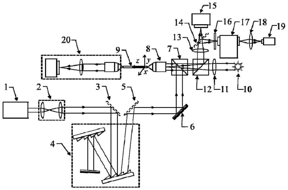
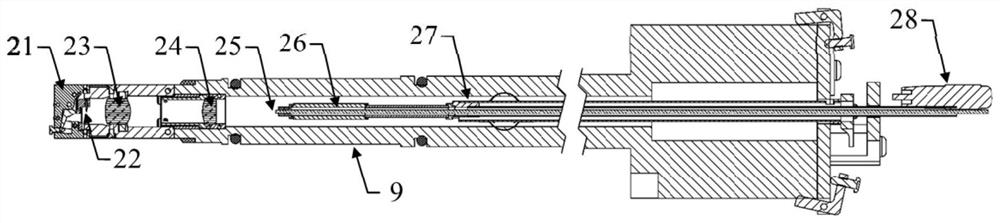
[0048] The present invention relates to transmission electron microscope sample holder systems with ultrafast time-resolved spectroscopy capabilities such as figure 1 As shown, it includes: a femtosecond laser 1, a beam expander collimator 2, a first flip mirror 3, a dispersion compensation element 4, a second flip mirror 5, a mirror 6, a first dichroic prism 7, and a microscope objective lens 8 , the sample bar 9 that fiber optic bundle is installed, white light source 10, the first lens 11, the second dichroic prism 12, the second lens 13, the third flip mirror 14, image acquisition device 15, optical filter 16, spectrometer 17, The third lens 18, the time-correlated single photon counter 19, the auxiliary optical imaging system 20; the detailed information of the sample rod part equipped with the fiber bundle is as attached figur...

Embodiment 2

[0053] This embodiment is used to illustrate the use method of the transmission electron microscope sample rod system of the present invention.

[0054] The specific implementation steps are as follows:

[0055] Step 1: The horizontally polarized light emitted by the femtosecond laser is first transformed into quasi-parallel light through the beam expander and collimator 2;

[0056] Step 2: passing the quasi-parallel femtosecond pulsed light obtained in step 1 through a grating pair to generate negative group velocity dispersion;

[0057] Step 3: focusing the broadened pulse light caused by the negative group velocity dispersion obtained in step 2 through the microscope objective lens 8 to the near end of the optical fiber bundle installed in the sample rod;

[0058] Step 4: irradiate the entire end face of the proximal end of the optical fiber bundle with the white light source 10 through the lens and the microscope objective lens 8;

[0059] Step 5: adjust the proximal end...


PUM

PropertyMeasurementUnit
sizeaaaaaaaaaa

Abstract

The invention discloses a transmission electron microscope sample rod system with ultra-fast time-resolved spectrum capability, which at least includes an optical fiber system composed of a sample rod installed with an optical fiber, an ultra-fast laser, a dispersion compensation element, a spectrometer, and a time-correlated single photon counter. system, and a mechanical system composed of piezoelectric ceramic tubes, differential micrometer heads, and three-dimensional displacement stages. The optical system and the mechanical system are to realize the in-situ focusing of pulsed light and the three-dimensional scanning of the focused spot in the transmission electron microscope, and the fluorescence and other signals excited and collected by the sample rod equipped with an optical fiber are finally utilized by the spectrometer Fluorescence spectra and fluorescence lifetimes were measured with a time-correlated single-photon counter. The invention realizes a transmission electron microscope sample rod system with ultra-fast time-resolved spectrum capability, which is used to introduce focused femtosecond pulse light into the transmission electron microscope, perform fluorescence spectrum characterization and fluorescence lifetime measurement, and realize ultra-fast Fast spectroscopy measurements.

Description

technical field [0001] The present invention relates to the technical field of transmission electron microscope accessories, in particular to a transmission electron microscope sample rod system with ultrafast time-resolved spectral capabilities and its application, more specifically, to a transmission electron microscope with ultrafast pulse optical focusing and ultrafast time-resolved spectral capabilities. Electron microscope sample rod and corresponding transmission electron microscope system. Background technique [0002] Exploring the correspondence between the structural properties of materials and their physical properties is one of the hotspots in the research of condensed matter physics. In the study of condensed matter physics, when the scale of a solid approaches its quantum characteristic length in one or more dimensions, due to the influence of quantum confinement effect and quantum fluctuation effect, it will show electronic structure characteristics that are ...

Claims


Application Information

Patent Timeline
Patent Type & Authority Patents(China)
IPC IPC(8): G01N21/64G02B21/00
CPCG01N21/6458G02B21/0036G02B21/0076G01N2021/6463G01N2021/6417
Inventor 马超杰刘畅孙华聪刘开辉王恩哥白雪冬
Owner INST OF PHYSICS - CHINESE ACAD OF SCI
Why Eureka
Try Eureka