Rapid dewatering and crushing device for metal powder material production
A rapid dehydration and metal powder technology, applied in heating devices, metal processing equipment, transportation and packaging, etc., can solve the problems of inconvenient screening of large particles, inconvenient rapid dehydration treatment, inability to pulverize thoroughly, etc. The drying effect is fast and efficient, the drying is uniform and thorough, and the effect of convenient crushing
- Summary
- Abstract
- Description
- Claims
- Application Information
AI Technical Summary
Problems solved by technology
Method used
Image
Examples
Embodiment 1
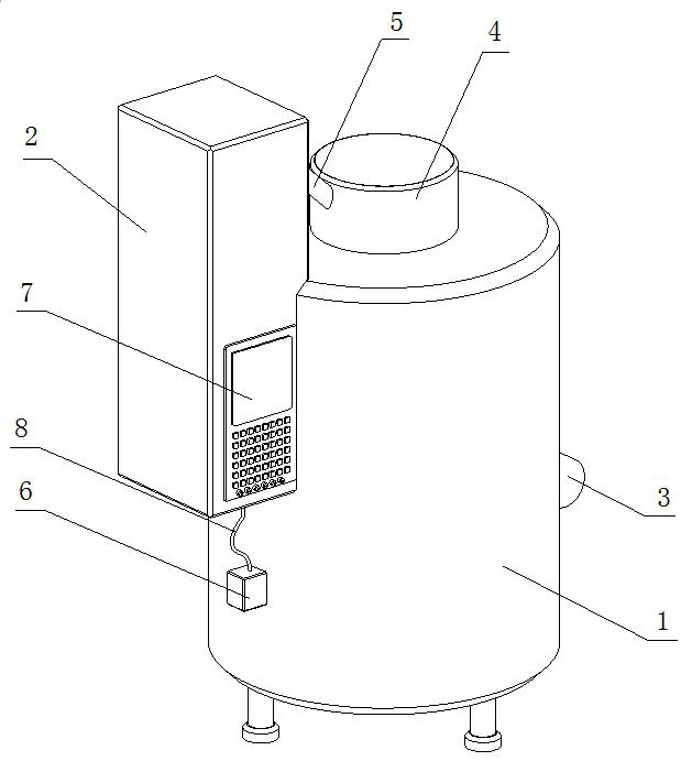
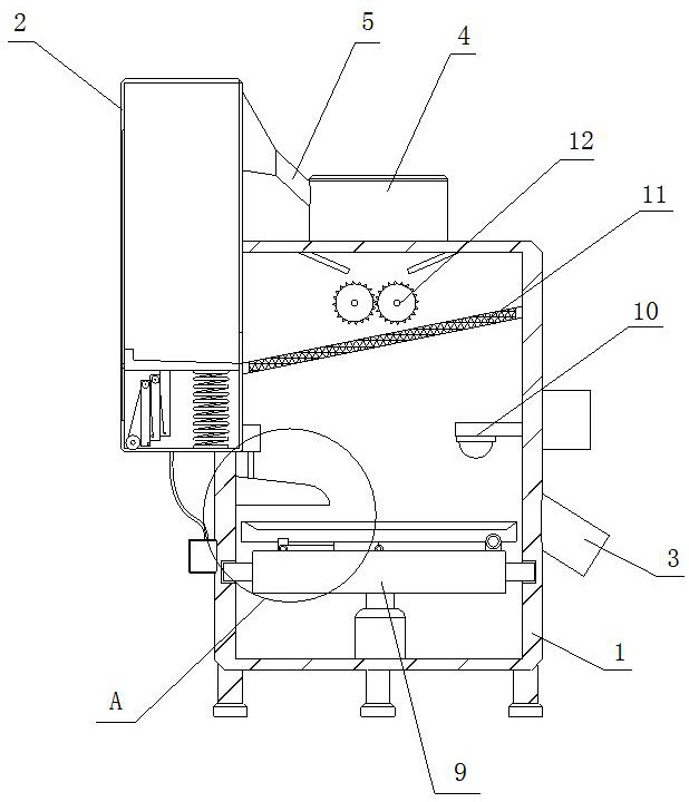
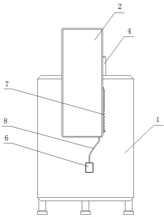
[0027] see Figure 1-6 , the present invention provides a technical solution: a rapid dehydration and crushing device for the production of metal powder materials, including a main body 1, one side of the outer wall of the main body 1 is fixedly connected with a material conveying device 2, and the main body 1 is far away from a part of the material conveying device 2 The side outer wall is fixedly connected with a lower hopper 3, the top of the main body 1 is fixedly connected with a feeding hopper 4, one side of the feeding hopper 4 is fixedly connected with a feeding pipe 5, and the outer wall of the main body 1 close to the feeding device 2 is fixedly connected with a The connector 6, the outer wall of the transport device 2 is fixedly connected with the control device 7, the bottom of the control device 7 is fixedly connected with the connecting line 8, the bottom inner wall of the main body 1 is fixedly connected with the rotating device 9, and the inner wall of one side ...
Embodiment 2
[0030] like Figure 1-6 As shown, on the basis of Embodiment 1, the present invention provides a technical solution: the rotating device 9 includes a driving motor 901, the top of the driving motor 901 is connected with a motor shaft for rotation, and the outer wall of the motor shaft is fixedly connected with a rotating plate 902, which rotates The outer wall of the plate 902 is fixedly connected with a tension spring 903, the side of the tension spring 903 far away from the rotating plate 902 is fixedly connected with a fixed block 904, one side of the fixed block 904 is fixedly connected with a rotating disk 905, and the inner wall of the main body 1 is fixedly connected with a Fixed plate 906, the inner wall of fixed plate 906 is fixedly connected with extruding spring 907, the other side of extruding spring 907 is fixedly connected with wedge-shaped block 908, and the side of fixed plate 906 away from fixed block 904 is hinged with hydraulic cylinder 909, hydraulic cylinde...
Embodiment 3
[0033] like Figure 1-7As shown, on the basis of Embodiment 1 and Embodiment 2, the present invention provides a technical solution: the material transport device 2 includes a material transport bin 201, and the bottom inner wall of the material transport bin 201 is fixedly connected with a return spring 202, and the return spring 202 The top of the feeder plate 203 is fixedly connected with a transport plate 203, the bottom of the transport bin 201 is rotatably connected with a wheel roller 204, the outer wall of the wheel roll 204 is wound with a steel wire rope 205, and the bottom of the material transport plate 203 is fixedly connected with a bar block 206, the bar block One side of the outer wall of 206 is fixedly connected with a fixed column 207, and the side of the delivery pipe 5 away from the feed hopper 4 is fixedly connected with the side of the outer wall of the delivery bin 201, and the top inner wall of the main body 1 is fixed at the position above the crushing ...
PUM
 Abstract
Description
Claims
Application Information
 - R&D
- Intellectual Property
- Life Sciences
- Materials
- Tech Scout
- Unparalleled Data Quality
- Higher Quality Content
- 60% Fewer Hallucinations
Browse by: Latest US Patents, China's latest patents, Technical Efficacy Thesaurus, Application Domain, Technology Topic, Popular Technical Reports.
© 2025 PatSnap. All rights reserved.Legal|Privacy policy|Modern Slavery Act Transparency Statement|Sitemap|About US| Contact US: help@patsnap.com


