Interphase wireless energy taking device

An energy-taking device and wireless technology, applied in the direction of circuit devices, transformers/inductor coils/windings/connections, transformers, etc., can solve the problems of heavy weight, increased installation and maintenance, and bulky volume, and achieve light weight and convenient installation and overhaul, small size effect

Pending Publication Date: 2021-03-16
北京瑞奇恩互感器设备有限公司
View PDF0 Cites 0 Cited by
  • Summary
  • Abstract
  • Description
  • Claims
  • Application Information

AI Technical Summary

Problems solved by technology

Although many field devices are close to the grid, they cannot directly obtain power from the high-voltage grid due to the limitation of the voltage level.
It is difficult to find a suitable power supply entry point or the correct feeding method, which has caused great obstacles to the application of power equipment condition monitoring devices
[0003] The voltage transformer based on the principle of electromagnetic sensing has an iron core inside, and the need for overcurrent protection is considered in the design. The weight of the iron core accounts for the main part of the product, especially the traditional voltage transformer is heavy and bulky, and the huge voltage The transformer increases the difficulty of installation and maintenance, and the long-term operation of the switch under such a load will have a great adverse effect on the mechanical life and safety
At the same time, due to the existence of the iron core, ferromagnetic resonance often occurs, causing the transformer to burn out and causing line failure.
[0004] Therefore, a technical solution for an energy harvesting device is currently needed to solve the problem of inconvenient installation and maintenance due to the heavy weight and bulky size of the traditional voltage transformer, and the long-term operation of the switch under such load conditions has great adverse effects on mechanical life and safety. The influence and the problem of ferromagnetic resonance and the problem of increased line leakage current caused by single phase-to-ground capacitance line

Method used


Image

  • Interphase wireless energy taking device
  • Interphase wireless energy taking device

Examples


Embodiment Construction

[0020] The technical solutions in the embodiments of the present invention will be clearly and completely described below with reference to the accompanying drawings in the embodiments of the present invention. Obviously, the described embodiments are only a part of the embodiments of the present invention, but not all of the embodiments. Based on the embodiments of the present invention, all other embodiments obtained by those of ordinary skill in the art without creative efforts shall fall within the protection scope of the present invention.

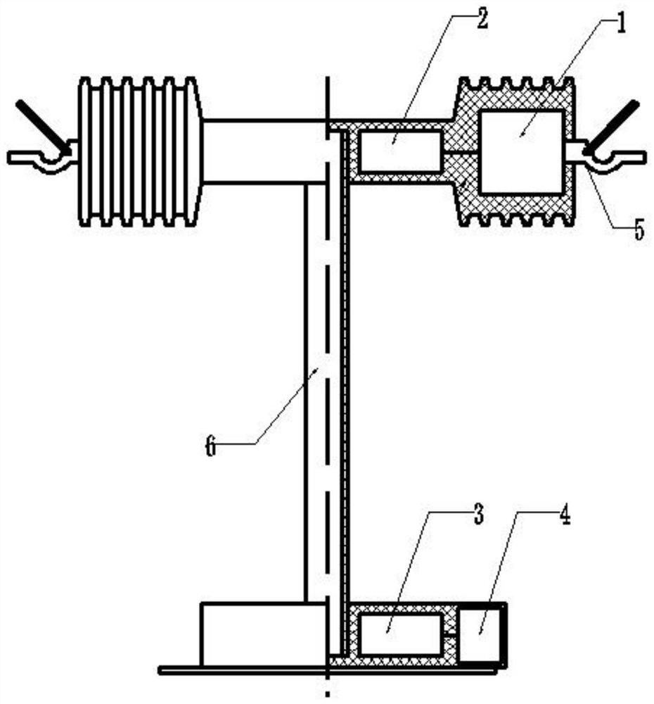
[0021] The technical problem to be solved by the present invention is to provide a technical solution of an energy harvesting device to solve the problem of inconvenient installation and maintenance caused by the heavy weight and bulky size of the traditional voltage transformer, and the long-term operation of the switch under such a heavy load will affect the mechanical life and safety. All have great adverse effects, as well as the p...


PUM


Abstract

The invention discloses a wireless energy taking device. The wireless energy taking device comprises a high-voltage capacitor; a transmitting coil connected with the voltage capacitor; a receiving coil arranged opposite to the transmitting coil; and an isolation transformer connected with the receiving coil. According to the embodiment of the invention, the wireless energy taking device is installed between two phases of conductors of a power transmission and distribution line, and the voltage and current levels applied to the transmitting coil are adjusted through the cooperation of the high-voltage capacitors at the two ends and the matched transmitting coil in the middle, so that a strong space electromagnetic field is generated in the transmitting coil; then the electromagnetic field is subjected to energy receiving through a low-voltage receiving coil, and after voltage regulation is carried out through an isolation transformer, primary high-voltage electric energy is transmittedto secondary low-voltage electric equipment for use; and the wireless energy taking device is small in size and high in precision, can obtain electric energy needed by an electric device from a powerdistribution overhead line, is small in size, light in weight and convenient to install and overhaul, and meets the requirement for intelligent development of an electric power system.

Description

technical field [0001] The invention relates to the field of electrical equipment, in particular to an interphase wireless energy harvesting device. Background technique [0002] With the promotion of smart grid technology and condition-based maintenance technology, in addition to traditional power equipment, more information collection, transmission and processing devices will be added to the future power grid. The power equipment status monitoring device installed in a high-voltage environment with strong magnetic field and strong electric field radiation has powerful data detection, data processing and communication functions, but the development of its power supply method is relatively lagging behind. Although many field devices are close to the grid, they cannot directly obtain power from the high-voltage grid due to the limitation of the voltage level. It is difficult to find a suitable power supply entry point or a correct feeding method, which has caused great obsta...

Claims


Application Information

Patent Timeline
Patent Type & Authority Applications(China)
IPC IPC(8): H02J50/10H01F38/14H01F27/28
CPCH01F27/28H01F38/14H02J50/10
Inventor 陈文玲韩冰
Owner 北京瑞奇恩互感器设备有限公司
Why Eureka
Try Eureka