Trace oxygen generation module and pure oxygen generation system thereof

Oxygen generation and trace technology, applied in the direction of cells, electrolysis process, electrode shape/type, etc., can solve the problem of increased contact resistance on the anode side and cathode side, so as to avoid the increase of input voltage, ensure the output, and excellent electricity The effect of contact performance

Active Publication Date: 2021-03-19
SHANGHAI JIAO TONG UNIV
View PDF11 Cites 5 Cited by
  • Summary
  • Abstract
  • Description
  • Claims
  • Application Information

AI Technical Summary

Problems solved by technology

[0007] The invention provides a trace oxygen generation module and its pure oxygen generation system, which can solve the technical problem of increased contact resistance between the anode side and the cathode side caused by assembly problems

Method used


Image

  • Trace oxygen generation module and pure oxygen generation system thereof
  • Trace oxygen generation module and pure oxygen generation system thereof
  • Trace oxygen generation module and pure oxygen generation system thereof

Examples


Embodiment

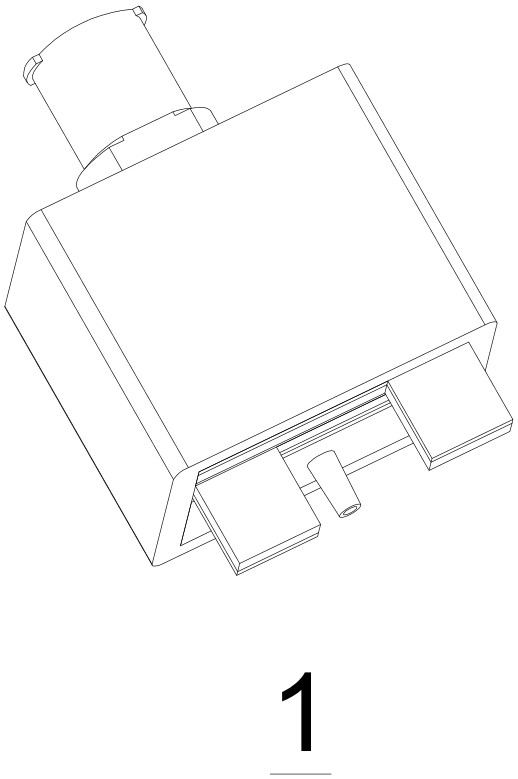
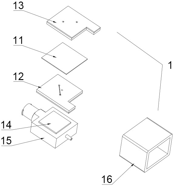
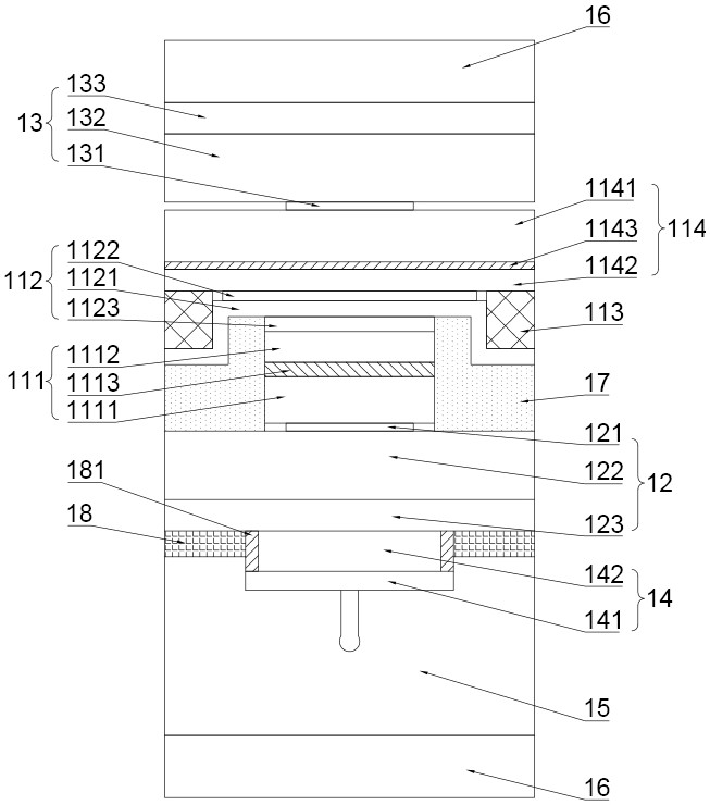
[0036] Trace oxygen generation module 1, such as Figure 1~Figure 6 As shown, it includes a cathode collector plate 13, a cathode support layer 114, a catalytic reaction layer 112, an anode support layer 111, and an anode collector plate 12 ( figure 2 Middle 11 is a cathode support layer 114, a catalytic reaction layer 112, an anode support layer 111 laminated membrane electrode) and a pure oxygen gas collection chamber 15, the cathode collector plate 13 and the anode collector plate 12 are equipped with current collector lines, the cathode Both the support layer 114 and the anode support layer 111 are provided with a conductive base layer, and the hardness of the conductive base layer is lower than that of the current collecting circuit. pressure and can maintain the state of being partially or fully embedded in the conductive base layer. In this embodiment, the current collecting circuit has a long and thin structure, specifically a strip structure, which is convenient for...

experiment example

[0060] The material and preparation process of each layer structure of the trace oxygen generation module in the above embodiments of the present invention are described as follows.

[0061] Cathode conductive layer 133: tin sheet size (length, width, thickness) 21mm×21mm×0.3mm.

[0062] Cathode non-conductive layer 132: PETG (glycol-modified polyethylene terephthalate), with a size of 21mm×21mm×2mm.

[0063] Cathode current collecting circuit 131 : palladium plating, width 0.1 mm, thickness 0.1 mm, plasma deposition.

[0064] Cathode conductive base layer 1141 (including water-transfer agent material and hygroscopic material): water-transfer agent material and hygroscopic material are respectively made of simethicone and silicon dioxide. Mix in the solvent formed by propanol and deionized water, the mass ratio of simethicone, silicon dioxide, ethanol, isopropanol and deionized water is 30:4:150:100:300, mix well to form a water-based suspension After immersing the carbon fi...


PUM

PropertyMeasurementUnit
sizeaaaaaaaaaa

Abstract

The invention provides a trace oxygen generation module and a pure oxygen generation system thereof. The technical problem that the contact resistance of the anode side and the cathode side is increased due to the assembly problem can be solved. The trace oxygen generation module comprises a cathode current collection plate, a membrane electrode, an anode current collection plate and a pure oxygengas collection cavity which are sequentially stacked into a whole, the cathode current collection plate and the anode current collection plate are each provided with a current collection circuit, andthe cathode supporting layer and the anode supporting layer are each provided with a conductive substrate layer. The trace oxygen generation module is characterized in that the hardness of the conductive substrate layer is lower than that of the current collection circuit; and under the action of the pre-tightening force provided by wrapping of the binding piece, the current collection circuit and the conductive substrate layer extrude each other and can maintain a state of being partially or completely embedded into the conductive substrate layer. The current collection circuit can be partially or completely embedded into the conductive substrate layer, the end face of the side, adjacent to the conductive substrate layer, of the current collection circuit can be completely attached to the conductive substrate layer, tight contact is formed between the current collection circuit and the conductive substrate layer, and then contact resistance of the cathode side and the anode side canbe reduced.

Description

technical field [0001] The invention relates to the technical field of producing micro-flow pure oxygen through an electrochemical method, in particular to a miniature portable oxygen generator, in particular to a micro-oxygen generation module and a pure oxygen generation system thereof. Background technique [0002] Chinese patent CN103173781A discloses that by wrapping an insulating tape on the outside of the porous gas end plate, membrane electrode, oxygen end plate and internal gas collection base, the porous gas end plate and the cathode gas diffusion layer are closely attached, and the insulating tape wound on the outside Under confinement, the porous gas end plate will slightly arch, and a micro gap will be formed between the porous gas end plate and the cathode gas diffusion layer. This micro gap can only be found under microscopic conditions and cannot be recognized by the naked eye, resulting in an increase in contact resistance. , the collection effect is very po...

Claims


Application Information

Patent Timeline
Patent Type & Authority Applications(China)
IPC IPC(8): C25B1/04C25B9/65C25B9/70C25B9/19C25B11/02
CPCC25B1/04C25B11/02Y02E60/36
Inventor 胡鸣若
Owner SHANGHAI JIAO TONG UNIV
Why Eureka
Try Eureka