Low-loss glass ceramic planar optical waveguide and preparation method thereof
A technology of planar optical waveguide and glass ceramics, which is applied in the direction of optical waveguide and light guide, can solve the problems of reducing optical efficiency, etc., and achieve the effects of simple process, high output and yield, and simple preparation process
- Summary
- Abstract
- Description
- Claims
- Application Information
AI Technical Summary
Problems solved by technology
Method used
Image

Examples
Embodiment 1
[0014] Example 1: SiO 2 -30mol% SNO 2 : 0.5er 3+
[0015] Sncl, which is greater than 99.9%, according to the chemical measurement ratio 2 Er (no " 3 ) 3 , Citric acid and orthosilicate (TEOS) as raw materials. First put SNCL 2 Er (no " 3 ) 3 , TEOS and citric acid mixed, the molar ratio of citric acid and the metal ion was 1: 0.5, then the volume fraction was a mixture of 50% deionized water, stirred at 200 rpm for 16 h, resulting in a sol. The solution was filtered using a 200 nm filter, and the collected portion was used for dip. SiO 2 The glass was dipped on the glass, the immersion rate was 7 cm / min, and 30 deposited layers were deposited, and then dried at 900 ° C for 20 min. Finally, it was heated at 900 ° C for 3 h to obtain a glass ceramic planar optical waveguide.
Embodiment 2
[0016] Example 2: SiO 2 -30mol% SNO 2 : 0.4er 3+
[0017] Sncl, which is greater than 99.9%, according to the chemical measurement ratio 2 Er (no " 3 ) 3 , Citric acid and orthosilicate (TEOS) as raw materials. First put SNCL 2 Er (no " 3 ) 3 , TEOS and citric acid mixed, the molar ratio of citric acid and the metal ion was 1: 1, then the volume fraction was a mixture of 20% deionized water, and stirred at 300 rpm for 10 h, resulting in a sol. The solution was filtered using a 200 nm filter, and the collected portion was used for dip. SiO 2 The glass was dipped on the glass, the immersion rate was 7.5 cm / min, and 20 deposited layers were deposited. After the dip coating was dried at 800 ° C for 30 min. Finally, heating at 1100 ° C for 1 h, resulting in a glass ceramic planar optical waveguide.
Embodiment 3
[0018] Example 3: SiO 2 -30mol% SNO 2 : 0.3er 3+
[0019] Sncl, which is greater than 99.9%, according to the chemical measurement ratio 2 Er (no " 3 ) 3 , Citric acid and orthosilicate (TEOS) as raw materials. First put SNCL 2 Er (no " 3 ) 3 , TEOS and citric acid were mixed, the molar ratio of citric acid and the metal ion was 1: 0.75, and then the volume fraction was a mixture of 40% deionized water, stirred at 280 rpm for 12 h, resulting in a sol. The solution was filtered using a 200 nm filter, and the collected portion was used for dip. SiO 2 The dip coating was performed on the glass, the immersion rate was 7 cm / min, and 25 deposited layers were deposited, and the dried was dried at 850 ° C for 26 min. Finally, heating at 1000 ° C for 2 h, resulting in a glass ceramic planar optical waveguide.
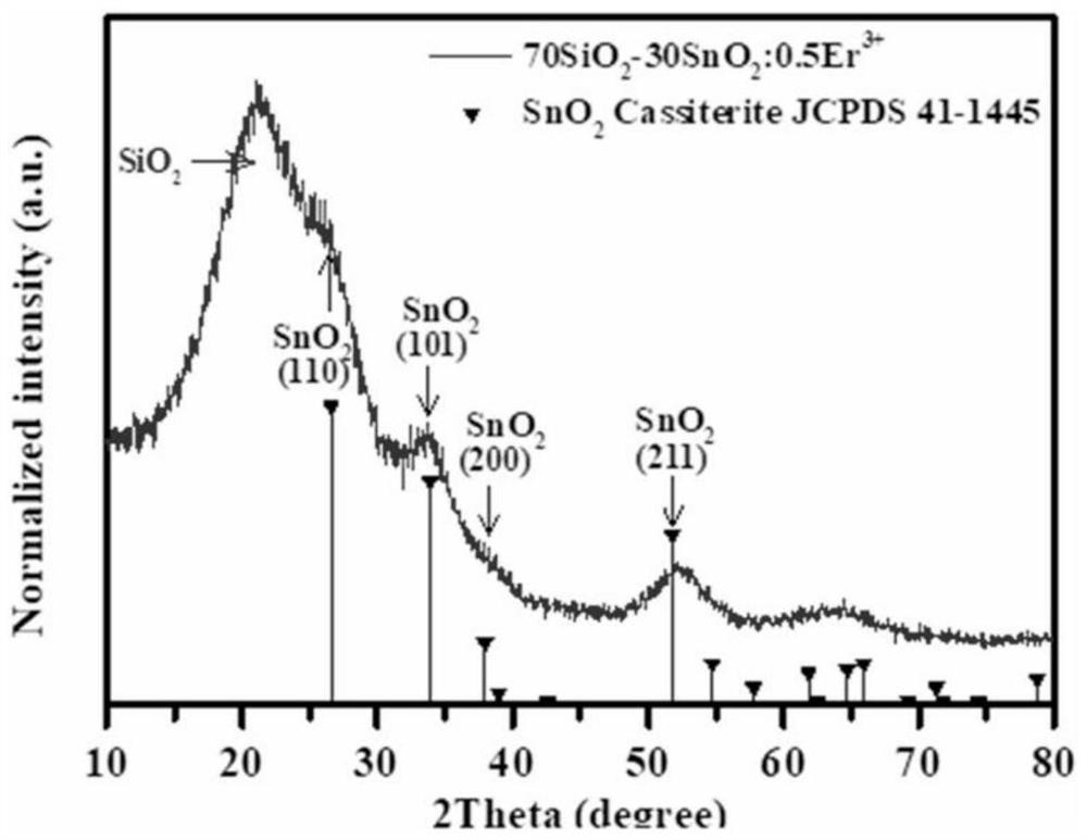
[0020] Take Example 1 as an example, from figure 1 XRD map shows, through comparison with standard cards, in SNO 2 The peak of the office has a good consistency, indicating succ...
PUM
 Abstract
Description
Claims
Application Information
 - R&D
- Intellectual Property
- Life Sciences
- Materials
- Tech Scout
- Unparalleled Data Quality
- Higher Quality Content
- 60% Fewer Hallucinations
Browse by: Latest US Patents, China's latest patents, Technical Efficacy Thesaurus, Application Domain, Technology Topic, Popular Technical Reports.
© 2025 PatSnap. All rights reserved.Legal|Privacy policy|Modern Slavery Act Transparency Statement|Sitemap|About US| Contact US: help@patsnap.com