
Membrane oxygenator

A membrane oxygenator and oxygenation technology, applied in the field of medical devices, can solve problems such as increased user cost, increased blood shear force, local turbulence, etc., to achieve uniform blood flow field distribution, small blood flow resistance, The effect of high oxygenation efficiency

Active Publication Date: 2021-03-26
成都市赛恒尔医疗科技有限公司
View PDF5 Cites 2 Cited by
  • Summary
  • Abstract
  • Description
  • Claims
  • Application Information

AI Technical Summary

Problems solved by technology

[0002] There is a contradiction in the design of the membrane lung parts of the extracorporeal circulation machine (ECMO): if the blood pump pressure and blood flow velocity are increased, the blood shear force will increase, leading to an increase in the probability of hemolysis and thrombosis; if the blood pump pressure is reduced, To reduce the blood flow rate, it is necessary to expand the diameter of the blood transfusion line and increase the capacity of the membrane oxygenator, so that more blood needs to be perfused into the line
Since ECMO perfusion needs to consume one-sixth of the blood volume of the human body, if the perfusion blood volume is further increased, other complications will be caused, which is also an unacceptable problem in clinical use
The existing technology is often a cartridge oxygenator. Because the flow field of blood in the membrane lung device is not easy to control, there are local turbulence and other phenomena, resulting in uneven blood shear force, causing problems such as thrombus and hemolysis, and affecting membrane lung parts. The service life of the membrane lung parts is increased, and the use cost of the user is increased; and the occurrence of thrombus can only be controlled by drugs to prolong the service life of the membrane lung parts

Method used


Image

  • Membrane oxygenator
  • Membrane oxygenator
  • Membrane oxygenator

Examples


Embodiment Construction

[0022] The present invention will be further described in detail below through specific embodiments in conjunction with the accompanying drawings. Wherein, similar elements in different implementations adopt associated similar element numbers. In the following implementation manners, many details are described for better understanding of the present application. However, those skilled in the art can readily recognize that some of the features can be omitted in different situations, or can be replaced by other elements, materials, and methods. In some cases, some operations related to the application are not shown or described in the description, this is to avoid the core part of the application being overwhelmed by too many descriptions, and for those skilled in the art, it is necessary to describe these operations in detail Relevant operations are not necessary, and they can fully understand the relevant operations according to the description in the specification and genera...


PUM


Abstract

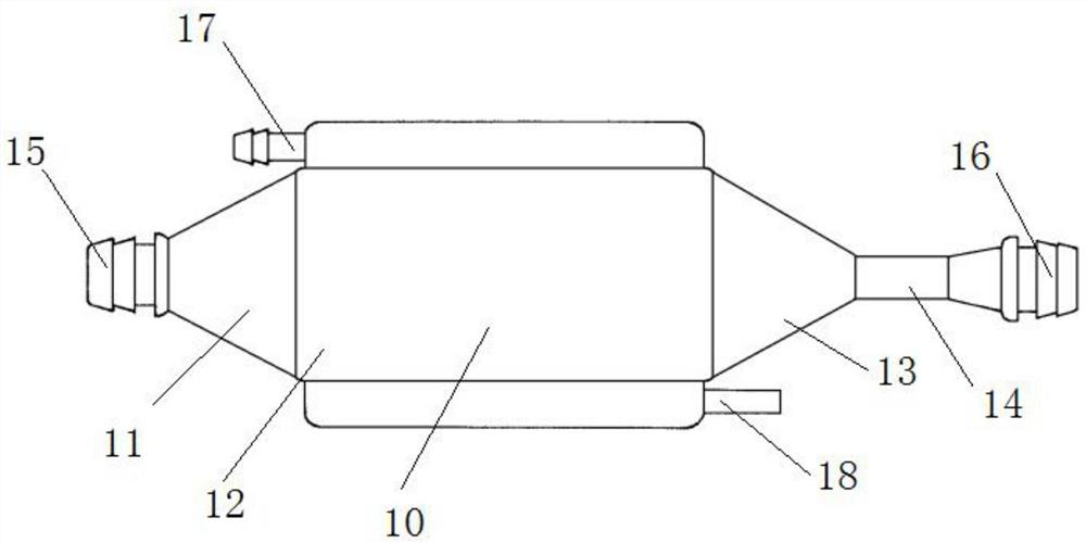
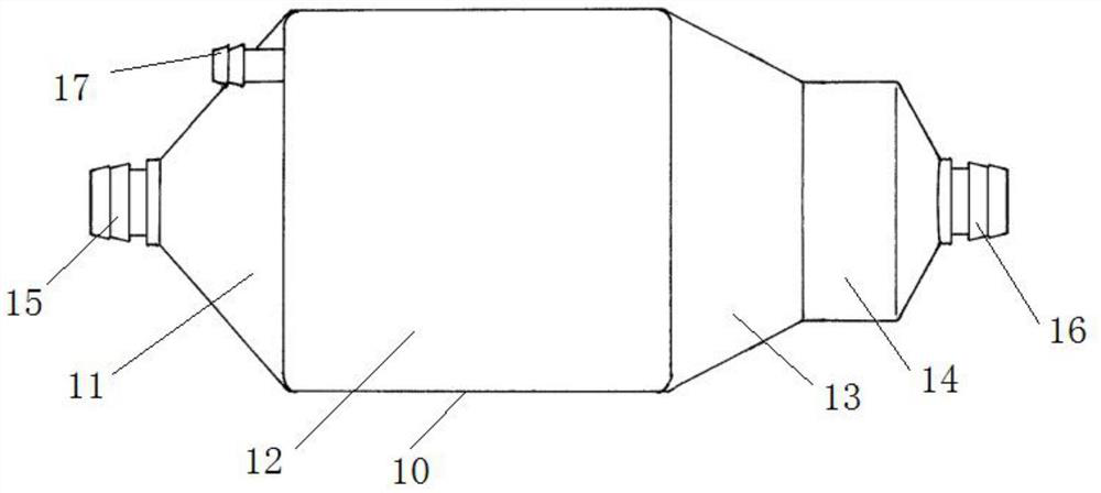
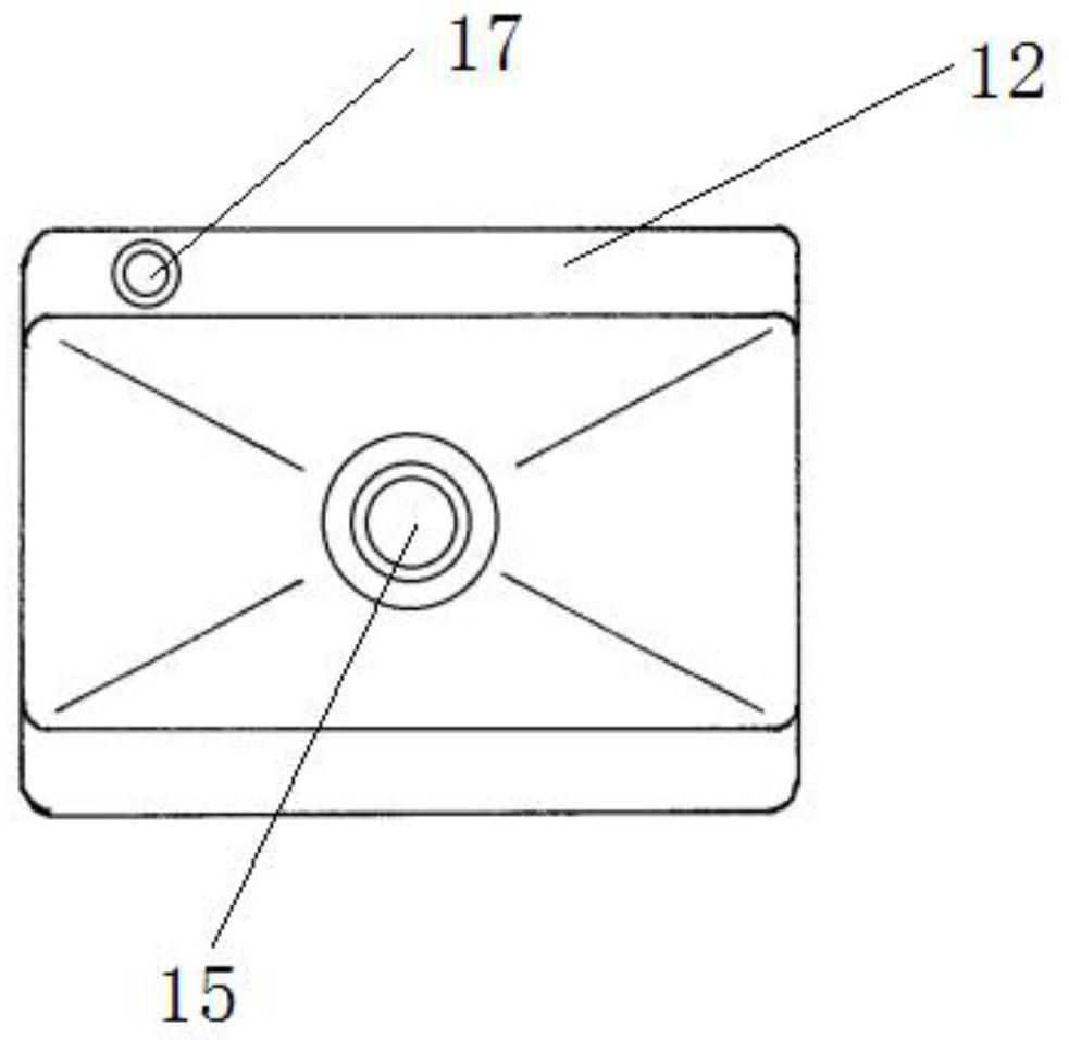
The invention relates to a membrane oxygenator. The membrane oxygenator comprises a cavity, a blood inlet and a blood outlet, wherein the blood inlet and the blood outlet are formed in two ends of thecavity; the cavity comprises a diffusion section, an oxygenation section, a gathering section and an observation section which sequentially communicate; the front end of the diffusion section is connected with the blood inlet; an oxygen inlet is formed in the upper part of the oxygenation section, a gas outlet is formed in the lower part of the oxygenation section, the oxygenation section is divided into a plurality of flow guide channels by a plurality of flow guide partition pieces in the cavity, and hollow oxygenation wires arranged in an array mode are arranged in the flow guide channels;and a flexible single-end free piece is connected to the tail part of each flow guide partition piece, and is located in the observation section, and the tail end of the observation section is connected with the blood outlet. In the process that blood passes through the oxygenator cavity in the radial direction, due to the fact that the first-order derivative of a flowing space sectional area iscontinuous and the second-order derivative of the flowing space sectional area is zero, a blood flow field is evenly distributed, and vortexes and dead zones are not generated.

Description

technical field [0001] The invention relates to the technical field of medical devices, in particular to a membrane oxygenator. Background technique [0002] There is a contradiction in the design of the membrane lung parts of the extracorporeal circulation machine (ECMO): if the blood pump pressure and blood flow velocity are increased, the blood shear force will increase, leading to an increase in the probability of hemolysis and thrombosis; if the blood pump pressure is reduced, To reduce the blood flow rate, it is necessary to expand the diameter of the blood transfusion tube and increase the capacity of the membrane oxygenator, so that more blood needs to be perfused into the tube. Since ECMO perfusion needs to consume one-sixth of the blood volume of the human body, if the perfusion blood volume is further increased, other complications will be caused, which is also an unacceptable problem in clinical use. The existing technology is often a cartridge oxygenator. Becau...

Claims


Application Information

Patent Timeline
IPC IPC(8): A61M1/16A61M1/36
CPCA61M1/1621A61M1/1625A61M1/1629A61M1/1698A61M1/3673A61M1/369A61M1/3621
Inventor 赖亚明黄健兵刘新黄洪辉
Owner 成都市赛恒尔医疗科技有限公司
Learn More