Combined denitration system and method for preheating section and tail flue of steel rolling heating furnace

A heating furnace and preheating section technology, applied in the field of flue gas denitrification, can solve the problems of increased production cost of steel rolling production enterprises, difficulty in accurately controlling the injection amount of ammonia gas, large fluctuation of steel rolling production, etc., and achieves good load adaptability and saving. The effect of external denitration space, reducing investment and operating costs

Pending Publication Date: 2021-03-26
NORTH CHINA UNIVERSITY OF SCIENCE AND TECHNOLOGY
View PDF6 Cites 1 Cited by
  • Summary
  • Abstract
  • Description
  • Claims
  • Application Information

AI Technical Summary

Problems solved by technology

[0004] (1) Steel rolling production fluctuates greatly, and the flue gas volume fluctuates greatly. When the flue gas volume fluctuates, it is difficult to accurately control the ammonia gas injection volume, and the ammonia escape index often exceeds the standard;
[0005] (2) During the roll changing process of the steel rolling heating furnace, the flue temperature drops below the working temperature of the medium and low temperature denitrification catalyst, which makes the catalyst invalid and leads to NO x Exceeding emission standards;
[0006] (3) The investment and operating costs of the flue gas denitrification system of the steel rolling heating furnace are high, which leads to an increase in the production cost of the steel rolling production enterprise

Method used


Image

  • Combined denitration system and method for preheating section and tail flue of steel rolling heating furnace

Examples


Embodiment 1

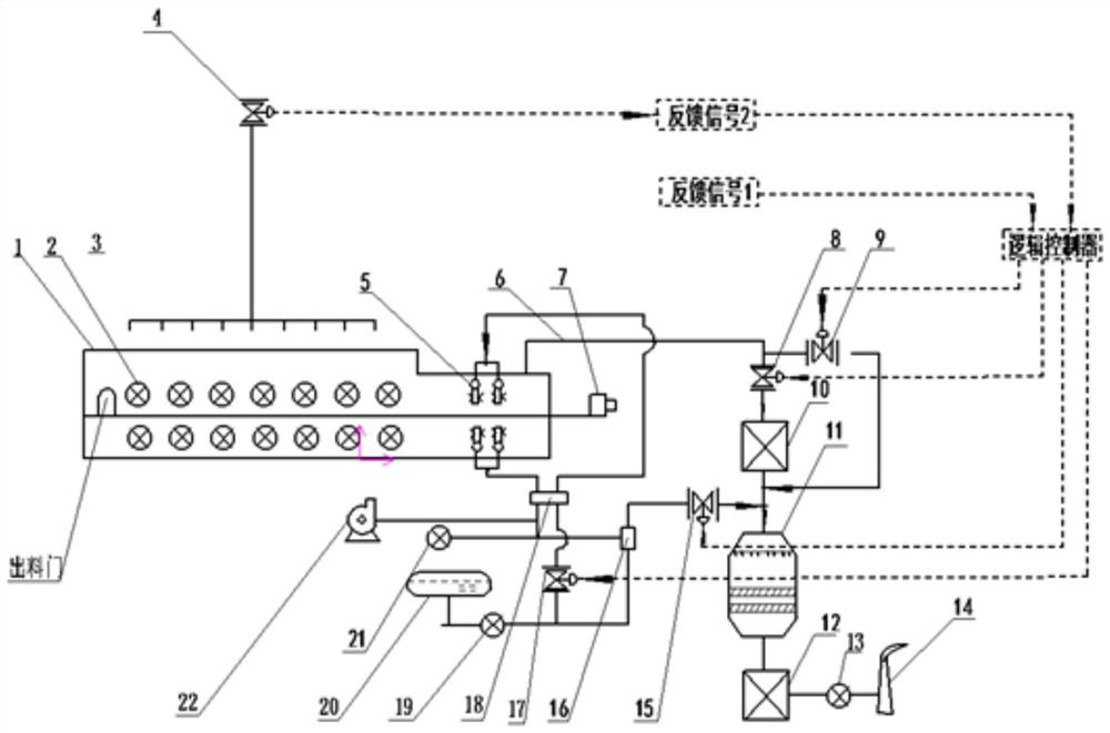
[0045] Such as figure 1 As shown, the joint denitrification system of the preheating section of the steel rolling heating furnace and the tail flue of the present invention includes a heating furnace, a steel pusher, an injection device, a high temperature air preheater, an SCR reactor, a low temperature air preheater, an SCR mixer, SNCR mixer, exhaust hood, air compressor, dilution fan, reducing agent storage device; the steel pusher is connected to the feeding end of the heating furnace for pushing the billet into the hearth of the heating furnace, and the injection device is set in the heating furnace The tail of the preheating section; the furnace roof at the feed end of the heating furnace is connected to the high-temperature air preheater, SCR reactor, low-temperature air preheater and exhaust hood in sequence through the flue gas pipeline to discharge the flue gas to the outside; reduction The reductant storage device is connected to the injection device through the SNCR ...

Embodiment 2

[0054] On the basis of Example 1, taking a steel rolling heating furnace in a steel plant as an example, the hourly flue gas volume is 90000Nm 3 / h, NO in the flue gas before installing the denitrification device x Concentration 350-420mg / Nm 3 .

[0055] After the above-mentioned heating furnace is equipped with the denitration system of the present invention, the SNCR system is installed in the preheating section of the heating furnace. Before the flue gas enters the SCR, it first passes through the two-stage high-temperature air preheater to cool down. In the flue, the flue gas passes through the SCR reactor and then passes through the first-stage low-temperature air preheater to cool down to below 150°C, and is discharged into the atmosphere through the induced draft fan.

[0056] When the two-stage denitrification process of SNCR and SCR is adopted, the total denitrification efficiency is over 95%, of which the SNCR denitrification efficiency is 40%, the SNCR denitrifica...

Embodiment 3

[0059] On the basis of embodiment 1, the denitrification method utilizing the combined denitrification system of the steel rolling heating furnace preheating section and tail flue of the present invention comprises the following steps:

[0060] (1) The reducing agent solution in the reducing agent storage device passes through the SNCR regulating valve according to the NO x The concentration of the reducing agent is adjusted, and it will be completely vaporized under the action of the air compressor and high temperature, so that the ammonia is converted into NH 3 After the gas is removed, it is sent to the SNCR mixer through the first reducing agent pipeline for mixing and standby;

[0061] (2) The steel pusher transports the steel billet to the furnace of the heating furnace, burns fuel in the burner to heat the steel billet, and generates high-temperature flue gas in the heating furnace. Spray the NH in step (1) 3 Gas reducing agent, so that it can be fully mixed with flue...


PUM


Abstract

The invention discloses a combined denitration system for a preheating section and a tail flue of a steel rolling heating furnace. The combined denitration system comprises a heating furnace, a steelpusher, a spraying device, a high-temperature air preheater, an SCR reactor, a low-temperature air preheater, an SCR mixer, an SNCR mixer, an exhaust hood, an air compressor, a dilution fan and a reducing agent storage device. The reducing agent storage device is connected with the SCR reactor through a second reducing agent pipeline via the SCR mixer; the air compressor is connected with the spraying device through an air pipeline via the SNCR mixer; the dilution fan is connected with the SCR mixer and the SCR reactor through a dilution pipeline; and a temperature control bypass flue is arranged between the inlet and the outlet of the high-temperature air preheater. According to the combined denitration process combining SNCR primary denitration arranged at the preheating section of the heating furnace and SCR secondary denitration arranged at the tail flue, the use amount of a reducing agent is controlled through an SCR regulating valve and an SNCR regulating valve, the use amount ofa catalyst is greatly reduced, the problem that NOx emission exceeds the standard in the roller changing period of the heating furnace can be effectively solved, and the investment and operation costof the system are reduced.

Description

technical field [0001] The invention belongs to the technical field of flue gas denitrification, and in particular relates to a combined denitrification system and method of a preheating section and a tail flue of a steel rolling heating furnace. Background technique [0002] Nitrogen oxides (NO x ) as a major atmospheric pollutant generally includes nitric oxide (NO), nitrogen dioxide (NO 2 ), nitrogen trioxide (N 2 o 3 ), nitrogen pentoxide (N 2 o 5 ), among which the main air pollution is NO and NO 2 . In recent years, with the increase of energy consumption, its emissions are also increasing year by year, and the environmental problems caused by it are also becoming more and more prominent. As the national environmental protection policy restricts the emission of air pollutants more and more strictly, for nitrogen oxides The reduction of emissions has also been gradually implemented in regulations and policies to strictly control the nitrogen oxides produced in th...

Claims


Application Information

Patent Timeline
Patent Type & Authority Applications(China)
IPC IPC(8): B01D53/90B01D53/79B01D53/56
CPCB01D53/90B01D53/79B01D53/56B01D2258/0283B01D2251/2062
Inventor 王子兵张磊徐杰姬爱民
Owner NORTH CHINA UNIVERSITY OF SCIENCE AND TECHNOLOGY
Why Eureka
Try Eureka