Production process for evaporative pattern centrifugal casting

A technology of centrifugal casting and production technology, which is applied in the direction of manufacturing tools, casting molding equipment, casting molds, etc., and can solve problems such as waste of manpower, difficulty in filling mold dead corners with molding sand, product quality, machining volume, and low work efficiency. Product output, reduce product processing allowance, improve the effect of density

Inactive Publication Date: 2021-03-26
洛阳佳会机械科技有限公司
View PDF11 Cites 1 Cited by
  • Summary
  • Abstract
  • Description
  • Claims
  • Application Information

AI Technical Summary

Problems solved by technology

[0004] The purpose of the present invention is to provide a production process for lost foam centrifugal casting, which combines lost foam casting and centrifugal casting to give full play to their respective advantages and solve the problem of packing (making) boxes in the prior art proposed in the above-mentioned background technology. Molding sand is not easy to fill the dead corners of the model, product quality problems and machining volume, not only the work efficiency is low, but also the problem of wasting a lot of manpower

Method used


Image

  • Production process for evaporative pattern centrifugal casting
  • Production process for evaporative pattern centrifugal casting
  • Production process for evaporative pattern centrifugal casting

Examples


Embodiment 1

[0068] See how Figure 1-14 Shown is a production process for lost foam centrifugal casting, comprising the following steps:

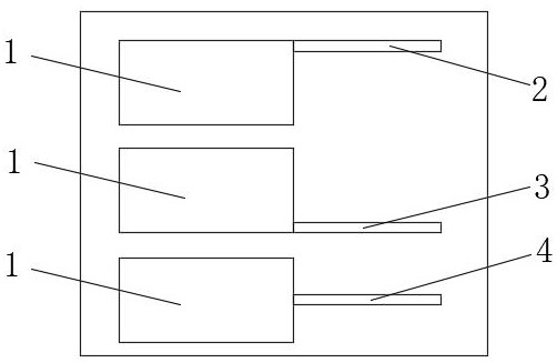
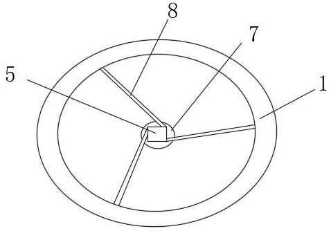
[0069] S1. Positioning of the sprue: including the runner 8, including the top pour 2, the bottom pour 3, and the middle pour 4. The direction of the sprue connection is consistent with the rotation direction of the casting 1, and the casting model is arranged;

[0070] S1.1. Vertical sprue 5: Connect the sprue at the top, place it vertically, and connect the runner or inner runner at the bottom (when the runner and inner runner are combined). The cross-section shape of the runner is round or square, and the appearance is cylindrical or columnar;

[0071] S1.2. Horizontal sprue 8: connected to the vertical sprue at the top, placed horizontally, and connected to the inner sprue at the bottom. The cross-section shape is square or round. When pouring two or more models at one time, the ends of the bottom surface of the horizontal and vertical runners ca...

Embodiment 2

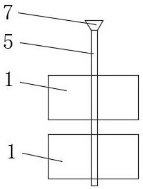
[0105] See how Figure 7 , a technical solution proposed by the present invention: the difference from Example 1 is: the design of the riser (slag collecting riser or feeding riser) in S2: the riser (slag collecting riser or feeding riser) It is placed close to the center and upper end of the model rotation, so that under the action of centrifugal force, slag and gas move from the casting to the riser (slag collection riser or feeding riser), and the riser (slag collection riser or feeding riser) Riser) is set vertically; the setting position is at the top of the casting.

Embodiment 3

[0107] See how Figure 8 , a technical solution proposed by the present invention: the difference from Example 1 is: the design of the riser (slag collecting riser or feeding riser) in S2: the riser (slag collecting riser or feeding riser) It is placed close to the center and upper end of the model rotation, so that under the action of centrifugal force, slag and gas move from the casting to the riser (slag collection riser or feeding riser), and the riser (slag collection riser or feeding riser) Riser) is set in an inclined direction; the set position is on the upper, middle and lower parts of the side of the casting.

[0108] Figure 8 Middle: vertical (straight) sprue can replace the riser (slag collecting riser or feeding riser)

[0109] In summary: the present invention is flexible in design: it provides sufficient degrees of freedom for the structural design of castings, and highly complex castings can be cast through the combination of foamed plastic molds; it reduces...


PUM


Abstract

The invention discloses a production process for evaporative pattern centrifugal casting. The production process comprises the following steps of S1, designing of a pouring gate; S2, designing of a riser; S3, a box loading (manufacturing) process; and S4, a pouring process. Meanwhile, a space with the size reduced due to solidification is filled with molten metal under the action of centrifugal force, and the feeding effect is good; meanwhile, a large number of crystal nuclei are generated through fracture of regrowth dendritic crystals under the action of the centrifugal force and exciting force, crystal grains are refined, and the density of a product is further improved; and the molten metal in the pouring gate and the riser (a slag collecting riser or a feeding riser) moves towards theinterior of a casting model under the action of the centrifugal force, the utilization rate of the molten metal is increased, the yield of centrifugal casting is also increased, and the machining amount of a centrifugal casting machine is reduced.

Description

technical field [0001] The invention belongs to the technical field of centrifugal casting, and in particular relates to a production process for lost foam centrifugal casting. Background technique [0002] Lost foam casting (also known as solid casting) is made of foam plastic (EPS, STMM or EPMM) polymer material to form a solid mold with exactly the same structure and size as the part to be cast, after dipping refractory coating (strengthening , bright and clean, air-permeable) and dried, buried in dry quartz sand and subjected to three-dimensional vibration modeling, pouring the molten metal into the casting mold sand box under negative pressure, so that the polymer material model is heated and gasified and drawn out, and then is cast Liquid metal replaces the one-time molding casting new technology formed after cooling and solidification to produce a new casting method for castings. Compared with traditional casting technology, lost foam casting technology has unparalle...

Claims


Application Information

Patent Timeline
Patent Type & Authority Applications(China)
IPC IPC(8): B22C9/04B22C9/08B22D13/00
CPCB22C9/046B22C9/082B22C9/088B22D13/00
Inventor 王会智郭乐乐王琪王钰
Owner 洛阳佳会机械科技有限公司
Why Eureka
Try Eureka