Supercritical carbon dioxide cogeneration system and operation method

A technology of cogeneration of carbon dioxide and heat and power, applied in the direction of combined combustion mitigation, steam engine installation, steam application, etc., can solve the problems of 50°C-140°C, difficulty in matching the heat release curve, difficulty in utilizing exhaust steam, etc. The effect of lowering the mass temperature, reducing the heat transfer temperature difference at the hot end, and improving energy utilization

Active Publication Date: 2021-03-26
XI AN JIAOTONG UNIV
View PDF11 Cites 0 Cited by
  • Summary
  • Abstract
  • Description
  • Claims
  • Application Information

AI Technical Summary

Problems solved by technology

[0005] At present, cogeneration units in northern my country mostly use high back pressure for heating or steam turbine extraction for heating, but in supercritical carbon dioxide systems, the exhaust steam pressure of the turbine is mostly below 10MPa. The heat is slow, and when it is lower than 60°C, the heat release curve is difficult to match, and it is easy to produce large irreversible losses. The waste heat required for heating is mostly between 50°C and 140°C. The heat supply of coal power generation system is different from the traditional high back pressure heating unit. Reasonable matching of energy levels and meeting the requirements of heating temperature and load are the problems that need to be solved in supercritical carbon dioxide power cycle.

Method used


Image

  • Supercritical carbon dioxide cogeneration system and operation method
  • Supercritical carbon dioxide cogeneration system and operation method
  • Supercritical carbon dioxide cogeneration system and operation method

Examples


Embodiment Construction

[0029] The present invention will be described in further detail below in conjunction with the accompanying drawings and specific embodiments.

[0030] working principle

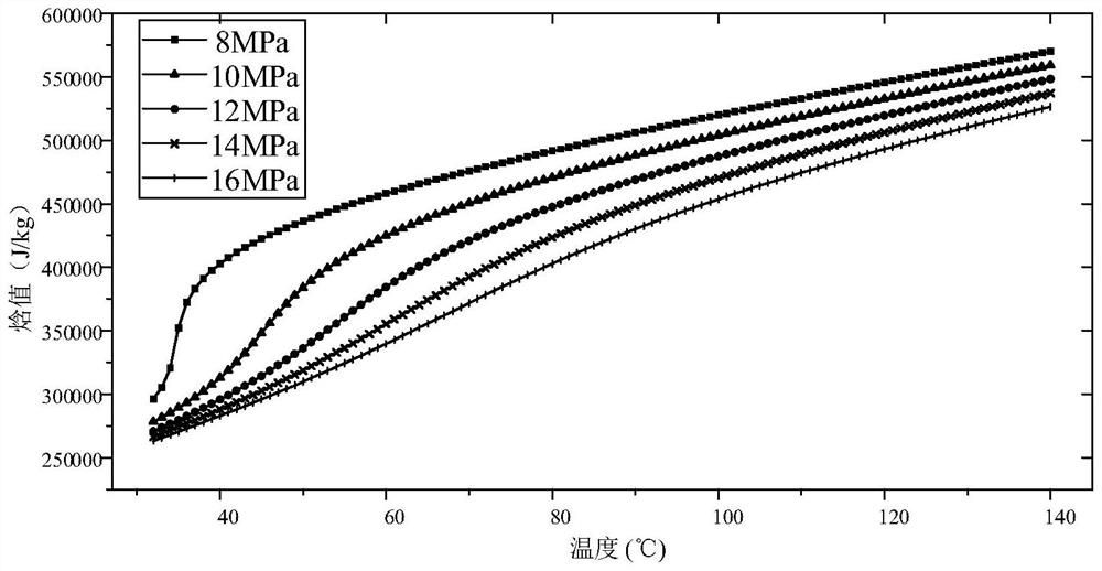
[0031] The curve of enthalpy value and temperature change of carbon dioxide working medium under different pressures is as follows: figure 1 As shown, in the supercritical carbon dioxide system, the exhaust steam pressure of the turbine is mostly below 10MPa. At this time, when the temperature of the working fluid is higher than 60°C, the heat release is slow. Irreversible loss, most of the waste heat required for heating is between 50°C and 140°C, and it is difficult to utilize exhaust steam in this temperature range, so the heat supply of supercritical carbon dioxide coal-fired power generation system is different from that of traditional high back pressure heating units. When the carbon dioxide pressure is high, the heat release curve is linear and easy to match, so it is a relatively reasonable and simp...


PUM


Abstract

The invention discloses a supercritical carbon dioxide cogeneration system and an operation method. A supercritical carbon dioxide cycle is adopted as a cogeneration power cycle, and an air exhaust-heat supply system is coupled, so that heat energy and electric energy are provided for a user at the same time; and through coupling optimization of a hot end-regeneration-heat supply process, the energy utilization rate of a supercritical carbon dioxide power system can be greatly increased. According to the system, reasonable energy level matching is conducted on air exhaust, and heat supply-airexhaust and a heat regenerative system are coupled, so that heat exchange irreversible losses in the system are reduced, different heat supply load requirements can be met by adjusting the carbon dioxide split ratio of the heat regenerative system, and the operation flexibility of a unit is improved; and the system can increase the temperature of a working medium entering a boiler, reduce the heatexchange temperature difference of a hot end, reduce the irreversible losses and improve the power generation efficiency of the unit while meeting the heat supply temperature.

Description

technical field [0001] The invention belongs to the field of cogeneration of heat and power, and in particular relates to a supercritical carbon dioxide cogeneration system and operation method. Background technique [0002] The stable growth of my country's economy is inseparable from the support of a strong energy system. my country's fossil energy structure is unbalanced, coal is the main body of my country's primary energy consumption, and coal-fired power generation is still the main power generation method in my country in a short period of time. As a large coal consumer in my country, thermal power units account for about 50% of the country's total coal consumption each year. [0003] my country's thermal power technology progress has shifted from improving initial parameters and steam reheating to full-working condition operation and deep utilization of waste heat. At the same time, central heating is carried out in the northern region to reduce pollutant emissions...

Claims


Application Information

Patent Timeline
Patent Type & Authority Applications(China)
IPC IPC(8): F01K25/10F01K7/32F01K17/06F01K7/38F01K13/02F01K17/02
CPCF01K25/103F01K7/32F01K17/06F01K7/345F01K7/38F01K13/02F01K17/02Y02E20/14
Inventor 刘明杨凯旋孙瑞强刘继平邢秦安严俊杰
Owner XI AN JIAOTONG UNIV
Why Eureka
Try Eureka