Sintering process based on coupling of sintering flue gas quality-divided circulation and flue gas pollutant emission reduction
A technology for sintering flue gas and pollutants, applied in separation methods, gas treatment, and separation of dispersed particles, etc., can solve the problems of large investment, high operating costs, and difficult disposal of waste catalysts
- Summary
- Abstract
- Description
- Claims
- Application Information
AI Technical Summary
Problems solved by technology
Method used
Image

Examples
Embodiment 1
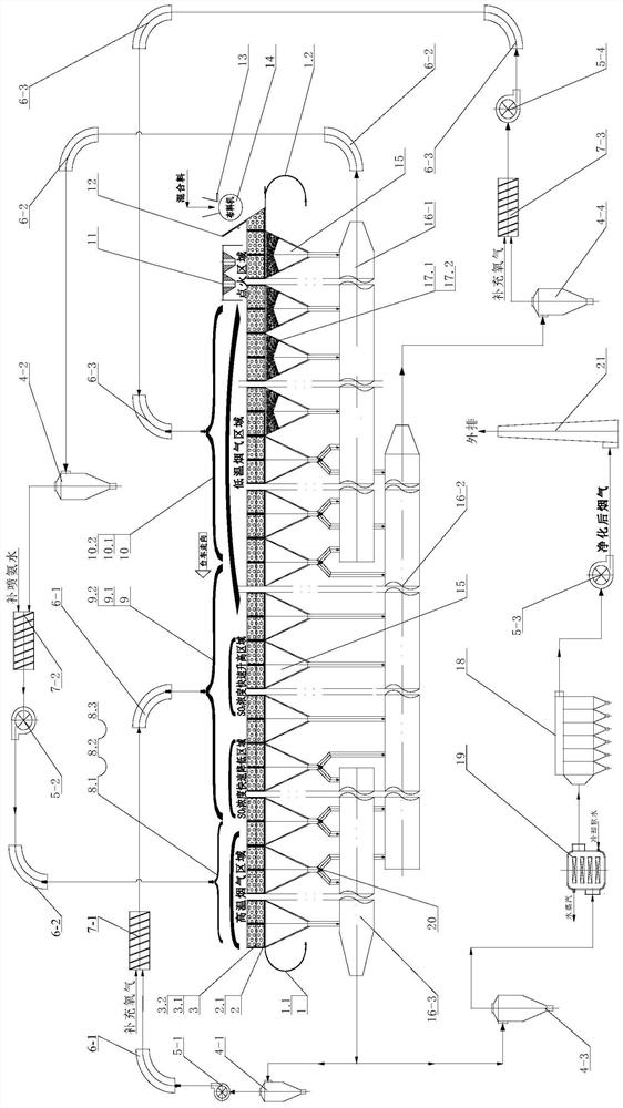
[0063] see figure 1 , including the sintering air flow in the fan (including high temperature circulating flue gas fan 5-1, low temperature circulating flue gas fan 5-2, high SO 2 The flue gas fan 5-4) passes through the 3 sintered material layer 3.1 of the sintered mixture, the sintered base material 3.2, the sintering machine 2, the trolley grate 2.1, the bellows 15 below the trolley 2.1 and enters the main flue (including Low temperature flue gas main flue 16-1, high SO 2 flue gas main flue 16-2, high temperature flue gas main flue 16-3); along the traveling direction of sintering machine 2 trolley 2.1, sintering machine 2 is divided into ignition area, low temperature flue gas area, SO 2 Rapidly increasing concentration area, SO 2 There are 5 areas, namely the rapidly decreasing concentration area and the high temperature flue gas area. The sintering mixture 3 is evenly distributed to the sintering machine 2 trolley 2.1 by the lowering hopper 13 and the distribution mac...
Embodiment 2
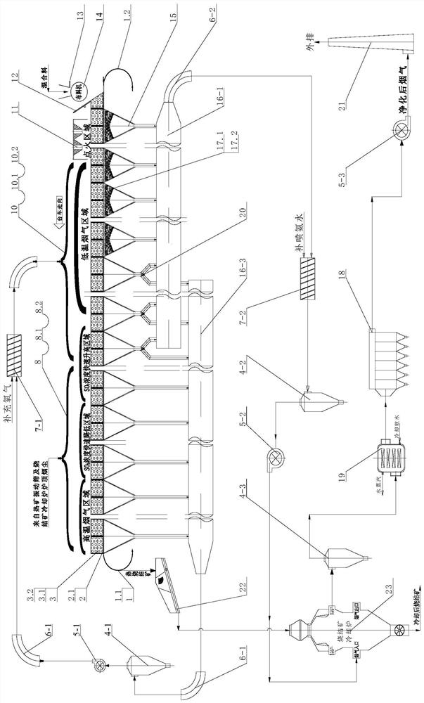
[0072] see figure 2 , including the sintering airflow passing through the sintering material layer 3.1 of the sintering mixture 3, the sintering base material 3.2, and the sintering machine 2 trolleys 2.1 grate, bellows 15 below trolley 2.1 enter the main flue (including low-temperature flue gas main flue 16-1, high-temperature flue gas main flue 16-3); Machine 2 is divided into ignition area, low-temperature flue gas area, SO 2 Rapidly increasing concentration area, SO 2 There are 5 areas, namely the rapidly decreasing concentration area and the high temperature flue gas area. The sintering mixture 3 is evenly distributed to the sintering machine 2 trolley 2.1 by the lowering hopper 13 and the distribution machine 14, and through the lowering chute 12. Driven by the rear trolley 2.1, the trolley 2.1 carrying the sintered material layer 3.1 and the sintered bottom material 3.2 advances to the bottom of the ignition system 11, and ignites and sinters. Under the suction eff...
Embodiment example 3
[0078] see figure 1 , including the sintering air flow in the fan (including high temperature circulating flue gas fan 5-1, low temperature circulating flue gas fan 5-2, high SO 2 The flue gas fan 5-4) passes through the 3 sintered material layer 3.1 of the sintered mixture, the sintered base material 3.2, the sintering machine 2, the trolley grate 2.1, the bellows 15 below the trolley 2.1 and enters the main flue (including Low temperature flue gas main flue 16-1, high SO 2 flue gas main flue 16-2, high temperature flue gas main flue 16-3); along the traveling direction of sintering machine 2 trolley 2.1, sintering machine 2 is divided into ignition area, low temperature flue gas area, SO 2 Rapidly increasing concentration area, SO 2 There are 5 areas, namely the rapidly decreasing concentration area and the high temperature flue gas area. The sintering mixture 3 is evenly distributed to the sintering machine 2 trolley 2.1 by the lowering hopper 13 and the distribution mac...
PUM
 Abstract
Description
Claims
Application Information
 - R&D
- Intellectual Property
- Life Sciences
- Materials
- Tech Scout
- Unparalleled Data Quality
- Higher Quality Content
- 60% Fewer Hallucinations
Browse by: Latest US Patents, China's latest patents, Technical Efficacy Thesaurus, Application Domain, Technology Topic, Popular Technical Reports.
© 2025 PatSnap. All rights reserved.Legal|Privacy policy|Modern Slavery Act Transparency Statement|Sitemap|About US| Contact US: help@patsnap.com