Flue gas denitration system and method for boiler under full-load working condition

A full-load, flue gas technology, applied in separation methods, chemical instruments and methods, gas treatment, etc., can solve problems such as leakage, high safety risks, and poor variability in ammonia production processes

Pending Publication Date: 2021-04-02
XIAN THERMAL POWER RES INST CO LTD
View PDF5 Cites 1 Cited by
  • Summary
  • Abstract
  • Description
  • Claims
  • Application Information

AI Technical Summary

Problems solved by technology

At the same time, the selection of SCR denitrification reducing agent for coal-fired units basically focuses on three directions: 1) Liquid ammonia, the most commonly used denitration reducing agent at present, the main process is liquid ammonia evaporator→ammonia gas→ammonia spray grid, the process is simple , the initial investment and operating costs are low, but liquid ammonia is a major hazard source and the safety risk is high
2) Ammonia water, the main process is ammonia water evaporator-ammonia gas→ammonia injection grid, the process is simple and the operation cost is low, but the transportation cost of ammonia water is expensive, the storage and transportation equipment is large, there is a risk of leakage, and the safety risk is high
The urea hydrolysis system is complicated, the ammonia production process has poor variability with load, the initial investment is large and the later maintenance is large, and pipeline corrosion and crystallization are prone to occur; urea pyrolysis often uses hot primary air plus electric heater or gas-gas heat exchanger to operate The cost is high, and the system is complex and easy to cause crystallization; neither of these two methods can meet the complexity of the flexibility and peak regulation of the actual coal-fired unit, and the safety, economy and simplicity of the SCR denitrification device.

Method used


Image

  • Flue gas denitration system and method for boiler under full-load working condition

Examples


Embodiment Construction

[0028] The present invention will be further described in detail below in conjunction with specific examples, which are explanations of the present invention rather than limitations.

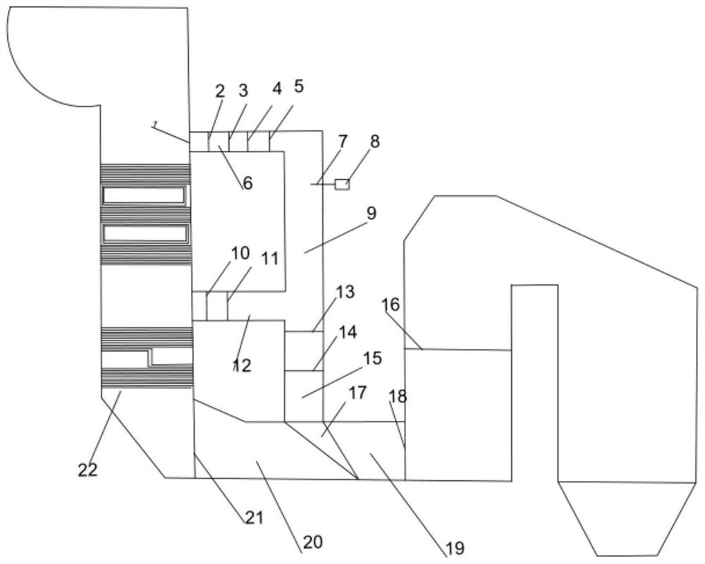
[0029] The present invention provides a flue gas denitrification system under the full load condition of the boiler, such as figure 1 As shown, it includes high-temperature flue gas leading flue 6, high-temperature flue gas introducing flue 12, low-load bypass introducing flue 15, low-temperature flue gas main flue 20, mixing flue 19, fly ash separator 1 on the boiler side , the first expansion joint 2, the first closing baffle door 3, the first adjusting baffle door 4, the second expansion joint 10, the second closing baffle door 11, the third expansion joint 13, the third closing baffle Panel door 14, urea direct injection pyrolysis flue 9, urea spray gun 7, urea solution metering module 8, high temperature fan 5, second adjustment baffle door 21, diversion groove 17, deflector 18, static mixe...


PUM


Abstract

The invention discloses a flue gas denitration system and method for a boiler under a full-load working condition. The system comprises a high-temperature flue gas bypass arranged outside a boiler flue in a connected mode. The high-temperature flue gas bypass comprises a high-temperature flue gas leading-out flue, a urea direct injection pyrolysis flue, a high-temperature flue gas leading-in flueand a low-load bypass leading-in flue. One end of the high-temperature flue gas leading-out flue is connected to a boiler rear flue turning chamber, and the other end is connected with the urea directinjection pyrolysis flue. The other end of the urea direct injection pyrolysis flue is respectively connected with one end of a high-temperature flue gas leading-in flue and one end of the low-load bypass leading-in flue. The other end of the high-temperature flue gas leading-in flue is connected to an inlet flue of an economizer. The other end of the low-load bypass leading-in flue is connectedwith a low-temperature flue gas main flue. The urea direct injection pyrolysis flue is connected with a urea spray gun. The spraying direction of the urea spray gun is perpendicular to the flow direction of flue gas in the urea direct injection pyrolysis flue. The system is reasonable in design and convenient to refit, meets the requirements of economy and safety and realizes flue gas denitrification under the full-load working condition of the boiler unit.

Description

technical field [0001] The invention relates to the field of boiler denitrification, in particular to a flue gas denitrification system and method under full-load boiler conditions. Background technique [0002] With the country's increasing investment in new energy power generation such as hydropower, wind power and solar power, the proportion of thermal power generation in the power industry has been decreasing year by year. The thermal power unit has gradually changed from the previous base load to the peak-shaving power supply of the grid. However, when a large number of existing coal-fired units are operating at low load, the flue gas temperature at the denitrification inlet cannot meet the minimum input temperature of the SCR system, resulting in low load NO x The discharge exceeds the standard, which affects the deep peak regulation of the unit. In order to meet the requirements of the national environmental protection policy and achieve the purpose of flexible peak ...

Claims


Application Information

Patent Timeline
Patent Type & Authority Applications(China)
IPC IPC(8): B01D53/86B01D53/56
CPCB01D53/8631B01D2258/0283B01D2251/2067
Inventor 袁壮董陈常磊黄尊对贾林权杨世极徐晓涛
Owner XIAN THERMAL POWER RES INST CO LTD
Why Eureka
Try Eureka