Turbulator welding robot system

A technology for welding robots and turbulators, applied in welding equipment, welding equipment, welding accessories, etc., can solve problems such as the inability to realize large-scale automatic welding of turbulators, the inability to use a laser visual positioning device, and the narrow space between blades. To achieve the effect of realizing automatic flow operation, improving welding efficiency and improving efficiency

Pending Publication Date: 2021-04-06
北京清新环境工程技术有限公司
View PDF0 Cites 0 Cited by
  • Summary
  • Abstract
  • Description
  • Claims
  • Application Information

AI Technical Summary

Problems solved by technology

[0003] In the processing process of the turbulencer in the prior art, because the blades of the turbulencer have multiple degrees of freedom in the space, and the space between the blades is narrow, it is impossible to use a laser or visual positioning device, resulting in the inability to realize the large size of the turbulencer. Batch automated welding

Method used


Image

  • Turbulator welding robot system
  • Turbulator welding robot system

Examples


Embodiment 1

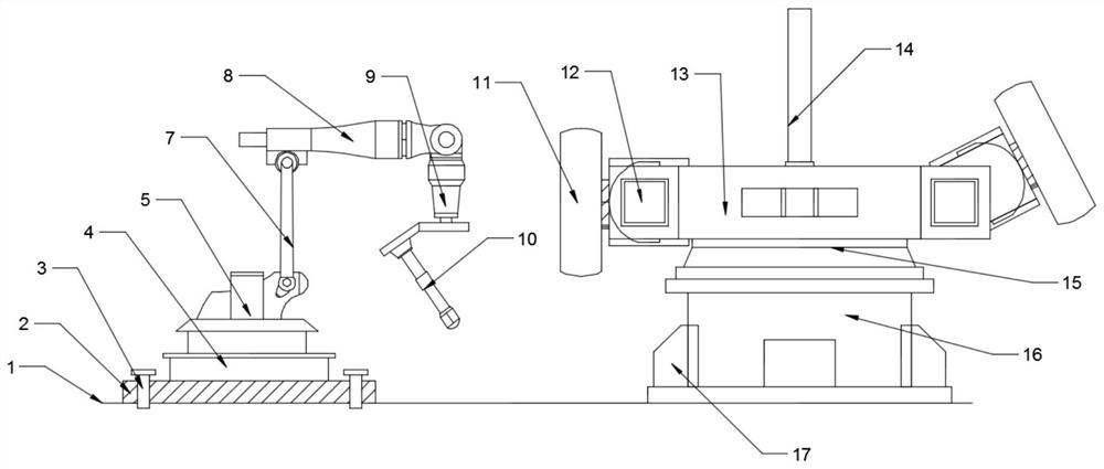
[0025] see figure 1 with figure 2 , in Embodiment 1 of the present invention, a turbulence welding robot system, which includes: a welding assembly and a displacement assembly, and the welding assembly and the displacement assembly are distributed on the left and right sides of the upper end of the ground 1;

[0026] The welding assembly includes a robot base 4, a first motor 5, a mounting frame 6 and a robot arm 7, the first motor 5 is arranged on the upper end of the robot base 4, the output end of the first motor 5 is connected with the mounting frame 6, and the mounting frame 6 upper end A robot arm 7 is movable, and the upper end of the robot arm 7 is provided with an installation terminal 8, and a laser displacement sensor 9 and an argon arc welding torch 10 are installed and fixed on one side of the installation terminal 8, and an anti-collision sensor is provided on the surface of the argon arc welding torch 10;

[0027] The displacement assembly includes a mounting ...

Embodiment 2

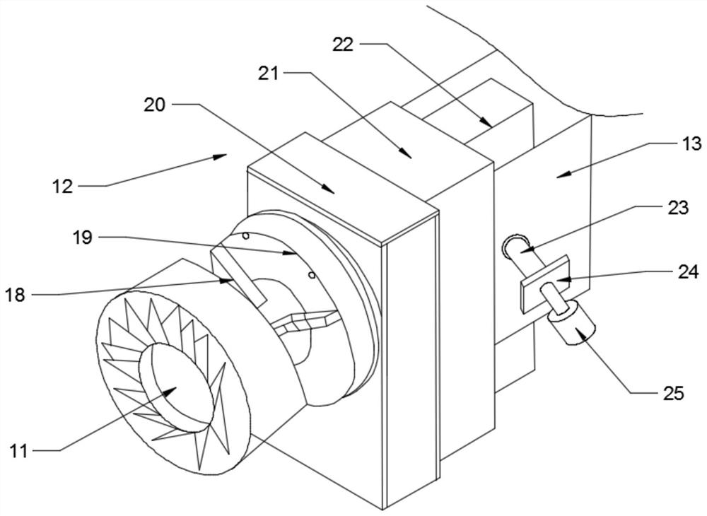
[0031] Further, the number of displacement mechanisms 12 is two, and the two displacement mechanisms 12 are distributed on the left and right sides of the mounting seat 13; through the two displacement mechanisms 12 provided, the two turbulator tooling 11 can be simultaneously adjusted in different states. Operation;

[0032] Specifically, the displacement mechanism 12 includes a clamping seat 19, a cylinder seat 20, an energy supply seat 21 and a rotating plate 22. The surface of the clamping seat 19 is provided with a three-jaw chuck 18, and the three-jaw chuck 18 is arranged on the clamping seat 19. The claw chuck 18 is driven to run by the cylinder block 20, the three-jaw chuck 18 is used to clamp and fix the turbulence tooling 11, one end of the cylinder block 20 is connected to the output shaft of the energy supply seat 21, and the other end of the energy supply seat 21 is installed and fixed with a rotating shaft. plate 22;

[0033] Furthermore, the rotating plate 22 i...


PUM


Abstract

The invention relates to the field of flue gas dust remover machining equipment, in particular to a turbulator welding robot system. The turbulator welding robot system comprises a welding assembly and position changing assemblies which are distributed on the left side and the right side of the upper end of the ground; the welding assembly comprises a robot base, a first motor, a mounting frame and a robot arm; and each position changing assembly comprises a mounting base, position changing mechanisms are arranged on the left side and the right side of the mounting base, the lower end of the mounting base is fixedly installed on a turntable, the lower end of the turntable is connected with an output shaft of a two-axis position changing machine base, and the two sides of the two-axis position changing machine base are fixedly installed on the ground through the arranged check blocks. According to the turbulator welding robot system, through the cooperative effect of the welding assembly and the position changing assemblies, automatic welding of a turbulator is achieved, and the welding operation efficiency of the turbulator is greatly improved.

Description

technical field [0001] The invention relates to the field of flue gas dust collector processing equipment, in particular to a turbulence welding robot system. Background technique [0002] Refrigerant is often used in the flue gas dust collector equipment. Due to the change of ambient temperature, the optimal balance point of the system and the state of the refrigerant inside each part will change, so the entire system cannot continue to operate stably and the efficiency is constantly changing; Therefore, it is necessary to optimize the operating state during the refrigerant cycle and install a turbulence device, so as to achieve the effect of improving the condition of the refrigeration unit, making it more energy-efficient, and increasing the life of the refrigeration system. [0003] In the processing process of the turbulencer in the prior art, because the blades of the turbulencer have multiple degrees of freedom in the space, and the space between the blades is narrow,...

Claims


Application Information

Patent Timeline
IPC IPC(8): B23K9/00B23K9/32B23K37/02B23K37/047
CPCB23K9/00B23K9/32B23K37/0252B23K37/047
Inventor 冯文宇朱波宇杨成祥
Owner 北京清新环境工程技术有限公司
Why Eureka
Try Eureka