Process for co-preparing hydrogen and LNG from raw gas

A waste gas and process technology, applied in hydrogen separation, petroleum industry, gas fuel, etc., can solve the problems of high compression energy consumption, waste of waste gas, and low impurity content of waste gas.

Active Publication Date: 2021-04-20
CHENGDU YIZHI TECH CO LTD +1
View PDF8 Cites 1 Cited by
  • Summary
  • Abstract
  • Description
  • Claims
  • Application Information

AI Technical Summary

Problems solved by technology

[0011](1) The technical solution recorded in the patent document "Application No.: 201810320196.0, Patent Name: A Process for Producing Hydrogen from Raw Coal Gas" can only Hydrogen is raised, other components of raw gas are wasted
[0012](2) Patent document "Application number: 201810042063.1, patent title: A method for producing hydrogen and LNG from coke oven gas" and application number: 201510850839.9, patent The title is: A process for producing metallurgical reduction gas and co-production of liquefied natural gas by using coke oven gas. Separating hydrogen an

Method used


Image

  • Process for co-preparing hydrogen and LNG from raw gas
  • Process for co-preparing hydrogen and LNG from raw gas
  • Process for co-preparing hydrogen and LNG from raw gas

Examples


Embodiment 1

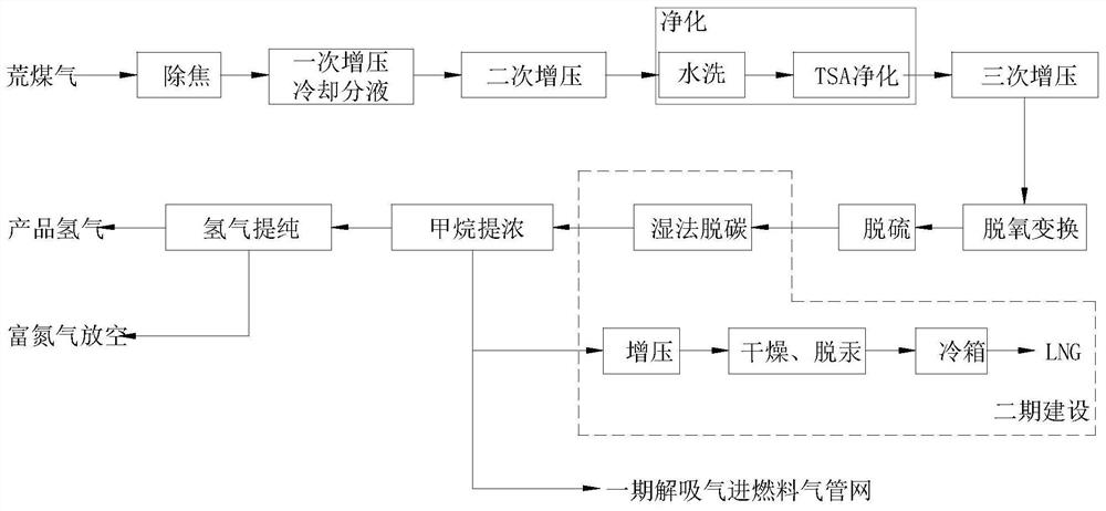
[0067] A raw coal gas hydrogen production co-production LNG process, specifically comprising the following steps:

[0068] Step 1: Decoking

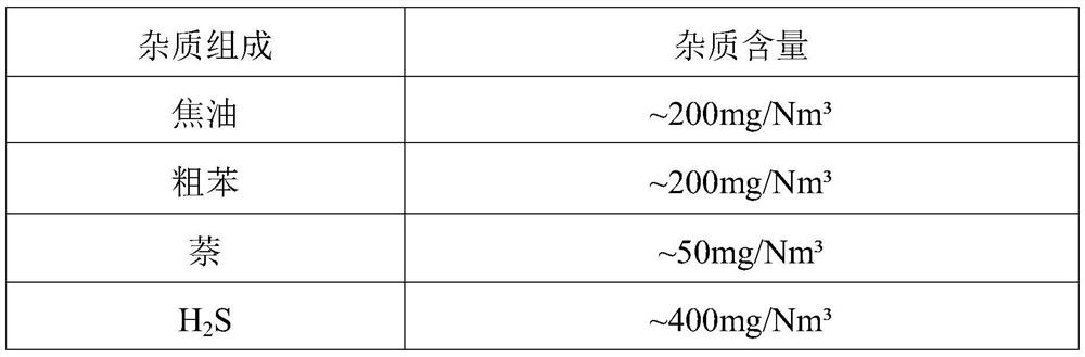
[0069] Remove the tar in raw raw gas by electrostatic decoker to obtain decoked raw gas, wherein the tar content in decoked raw gas is 20mg / Nm 3 the following. In the actual process, it can also be other decoking equipment that can play the same role.

[0070] Step 2: One boost cooling liquid separation

[0071] Pressurize the raw coal gas after decoking in step 1 to 0.07MPa, then cool the supercharged raw coal gas and perform gas-liquid separation, reduce the molar content of water in the decoked raw coal to 4.4%, and obtain a Supercharged raw gas. Among them, according to the characteristics of air volume and low compression ratio, the blower is selected in step 2 of this embodiment to pressurize the raw coal gas, and other pressurization equipment that can play the same role can also be used in the actual process.

[0072] Step 3...

Embodiment 2

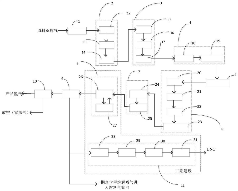
[0110] Such as figure 2 As mentioned above, the present invention also discloses a system for producing hydrogen from raw coal gas and co-producing LNG, which includes a decoking unit 1, a primary pressurized cooling liquid separation unit 2, a secondary pressurized unit 3, a pretreatment unit 4, and a three-stage Pressurization unit 5 , deoxygenation conversion unit 6 , desulfurization unit 7 , decarburization unit 8 , methane enrichment unit 9 , hydrogen purification unit 10 , and LNG production unit 11 .

[0111] Specifically, such as figure 2 As shown, an electrostatic decoker is used in the decoking unit 1 for removing tar in raw raw coal gas. In the actual operation process, there is at least one electrostatic decoker; specifically, the decoked raw gas is obtained after the tar is removed in the electrostatic decoker from the raw raw gas. In addition, the decoker in this embodiment can also be other equipment or a combination of equipment with the same function, and ...


PUM


Abstract

The invention discloses a process for co-preparing hydrogen and LNG from raw gas. The process sequentially comprises a decoking step, a primary pressurization cooling liquid separation step, a secondary pressurization step, a pretreatment step, a tertiary pressurization step, a deoxidation conversion step, a desulfurization step, a wet decarburization step, a methane concentration step, a hydrogen purification step and an LNG preparation step. According to the process, LNG is also prepared while hydrogen is prepared, so that effective components in the raw coke oven gas are fully utilized, and the waste of energy sources is reduced; besides, the raw coke oven gas is pressurized basically through three times of compression in different stages before CO conversion, so that the energy consumption of the whole process is reduced; in addition, impurities in the raw coke oven gas subjected to CO conversion are removed by adopting a vacuumizing pressure transformation system I and a vacuumizing pressure transformation system II to obtain product hydrogen with the purity as high as 99.9%, and the recovery rate of the hydrogen can reach 89% or above; and desorbed gas rich in methane is adsorbed and desorbed from the vacuum-pumping variable-pressure system 1 to be used for preparing LNG.

Description

technical field [0001] The invention relates to the technical field of raw gas treatment, in particular to a process for producing hydrogen from raw gas and co-producing LNG. Background technique [0002] Raw coal gas, also known as crude gas and coke oven gas, is unpurified gas produced by low-temperature dry distillation of coal. Its main components are shown in the following table: [0003] composition Raw gas (mol%) O 2 0.5~1.0 N 2 20~45 H 2 10~30 CO 10~20 CO 2 10~20 CH 4 5~10 cH 0.5~2 water saturated water [0004] In addition to the ingredients in the above table, raw coal gas also contains a small amount of tar, benzene, naphthalene, hydrogen sulfide, organic sulfur, HCN, NH 3 and other impurities. The content of impurities in common raw coal gas is shown in the table below: [0005] [0006] [0007] According to the different coal quality and treatment process, the components of r...

Claims


Application Information

Patent Timeline
IPC IPC(8): C01B3/50C10L3/10
Inventor 侯世杰余浩瞿孝星李振东曾轲梁东黄成波阎朝旭邹康刘贤虎
Owner CHENGDU YIZHI TECH CO LTD
Why Eureka
Try Eureka