Eureka AIR delivers breakthrough ideas for toughest innovation challenges, trusted by R&D personnel around the world.

Machining process for carrying out local solid solution strengthening on valve disc neck portion and valve rod

A technology of solid solution strengthening and processing technology, which can be used in manufacturing tools, furnaces, heat treatment equipment, etc., and can solve the problems of complex valve stem shape, complex process and high solution cost.

Pending Publication Date: 2021-04-20
赵毛兴
View PDF0 Cites 0 Cited by
  • Summary
  • Abstract
  • Description
  • Claims
  • Application Information

AI Technical Summary

Problems solved by technology

As we all know, solid solution costs are high, quality control is difficult, there are both time requirements and temperature requirements, the temperature processing range is small, and the overall shape of the valve stem is complex, resulting in uneven heating during heating, so the quality of the valve stem is poor and solid solution comes out The level of valve stem structure fluctuates greatly; at the same time, it is pointed out that in order to achieve the heat resistance of the valve, the grain size of the valve stem structure after solid solution must reach 3-6 grades to achieve the best high temperature creep strength; but things are two aspects Yes, after the grain size increases, although it meets the requirements of high temperature strengthening, its toughness becomes smaller. The upper umbrella part of the valve stem achieves this purpose, but the tail of the valve stem needs to be equipped with a lock clip to drive the valve stem. Up and down opening and closing work, the tail of the stem does not need a high-temperature-resistant coarse-grained structure, but a fine-grained structure with high toughness. In order to achieve this goal, the current valve stem processing technology generally adopts the disc part to be formed first for solution heat treatment. After the disc is corrected and processed, it is docked with a material with high structural toughness (martensitic material), and then the follow-up processes such as normalizing heat treatment and fine cutting are carried out.
This method has long processing cycle, complex process, high cost and high reject rate

Method used


Image

  • Machining process for carrying out local solid solution strengthening on valve disc neck portion and valve rod
  • Machining process for carrying out local solid solution strengthening on valve disc neck portion and valve rod
  • Machining process for carrying out local solid solution strengthening on valve disc neck portion and valve rod

Examples


Embodiment 1

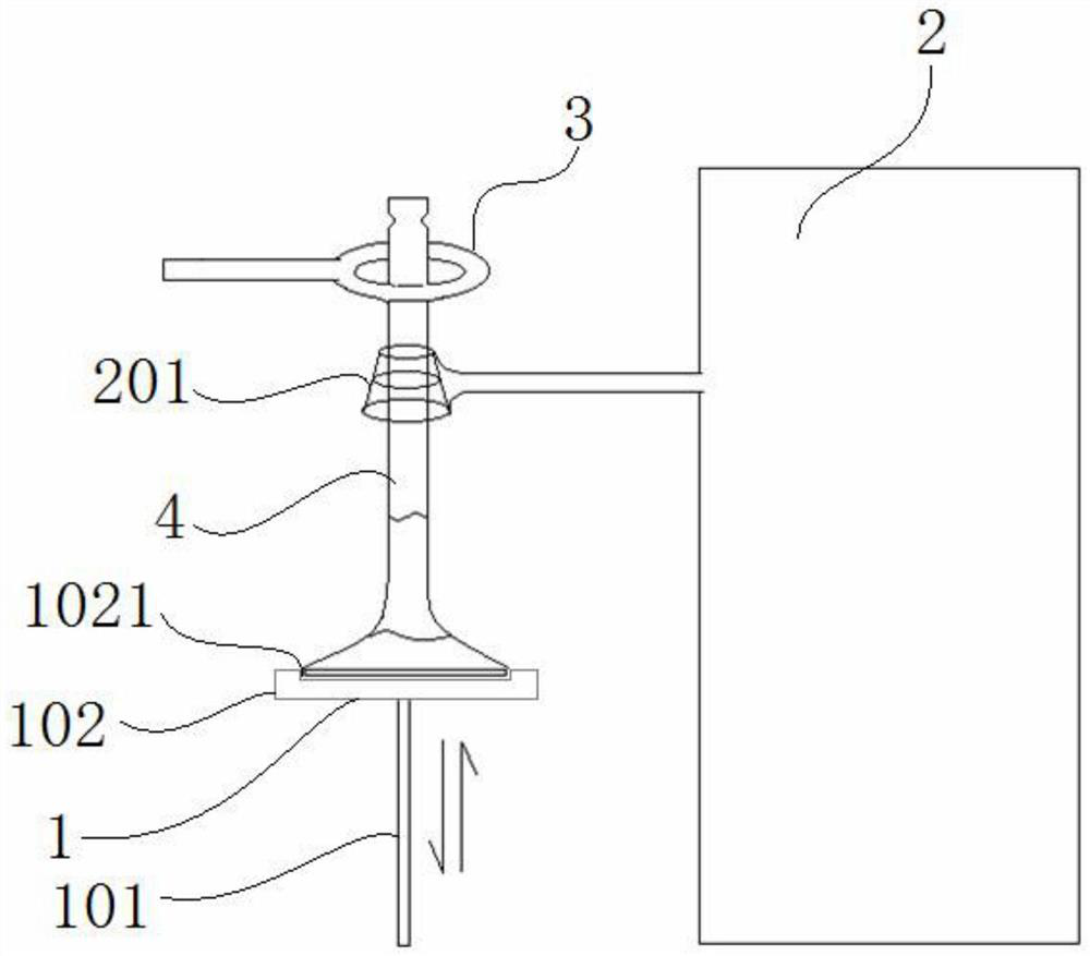
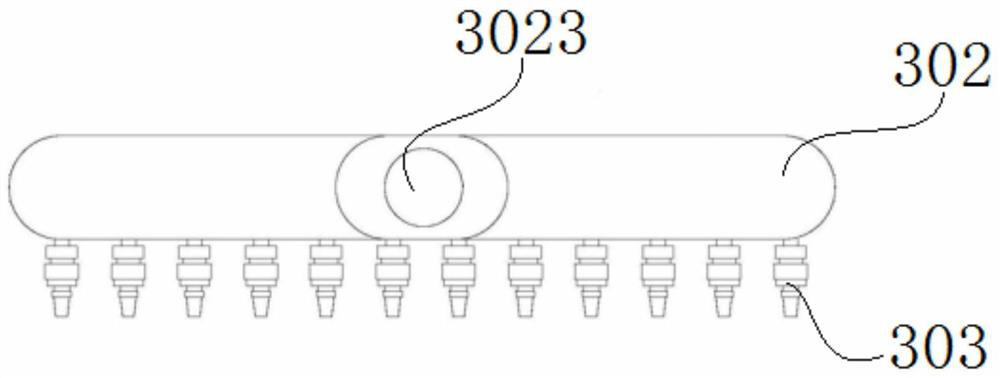
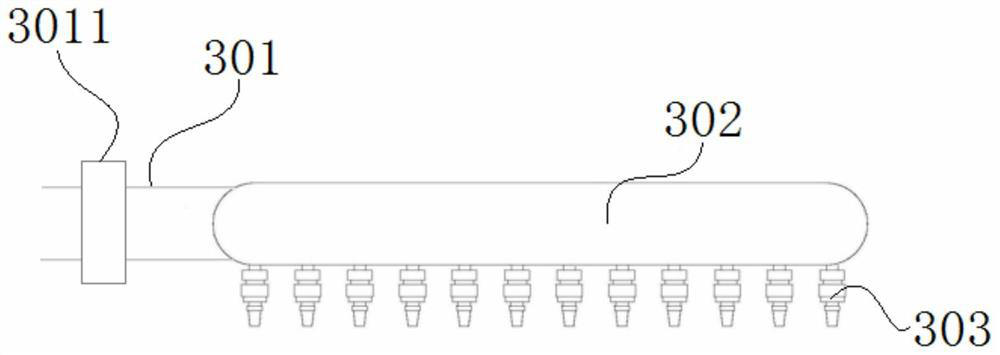
[0035]This example discloses a partial solid solution hardening process for the gas veneer neck, seeFigure 1 to 5 , Including the following steps:

[0036]1) Forming the valve rod blank 4 using a bacteric austenite valve steel material forging. Among them, the valve rod blank 4 is sequentially from the bottom to the umbrella portion 401, the tray 402, the rod portion 403, and the small end 404.

[0037]2) The small end 404 of the valve rod blank 4 and the umbrella portion 401 are solder.

[0038]3) Place the umbrella portion 401 of the valve rod blank 4 is placed on the positioning clamp assembly 102 of the feed positioning device 1. Wherein, the feed positioning device 1 includes a telescopic rod 101 and a positioning clamp assembly 102. The positioning clamp assembly 102 is fixed to the upper end portion of the telescopic rod 101. Specifically, the positioning clamp assembly 102 is a positioning plate, and there is a threaded hole on the bottom surface of the positioning plate, and the end...

Embodiment 2

[0052]This embodiment provides a relatively basic implementation, a local solid solution hard-dissolving processing process for the valve disc neck, seeFigure 1 to 5 , Including the following steps:

[0053]1) Forming valve rod blank 4. Among them, the valve rod blank 4 is sequentially from the bottom to the umbrella portion 401, the tray 402, the rod portion 403, and the small end 404.

[0054]2) Place the umbrella portion 401 of the valve rod blank 4 is placed on the positioning clamp assembly 102 of the feed positioning device 1. Wherein, the feed positioning device 1 includes a telescopic rod 101 and a positioning clamp assembly 102. The positioning clamp assembly 102 is fixed to the upper end portion of the telescopic rod 101. Specifically, the positioning clamp assembly 102 is a positioning plate, and there is a threaded hole on the bottom surface of the positioning plate, and the end of the telescopic rod 101 has an external thread, and the positioning plate 102 is fixed to the end...

Embodiment 3

[0067]In this example, the main step is to Example 2, in step 1), the valve rod blank 4 uses austenite material forging, the valve rod blank 4 is formed, and the small end 404 and an umbrella of the valve rod blank 4 are formed. 401 Perform alloy reactors.


PUM


Abstract

The invention discloses a machining process for carrying out local solid solution strengthening on a valve disc neck portion and a valve rod. The machining process comprises the steps that 1) a valve rod blank is formed; 2) the disc neck portion of the valve rod blank is heated and subjected to solid solution; 3) after heating and solid solution treatment are completed, the disc neck portion of the valve rod blank is subjected to cooling treatment; and 4) the valve rod blank returns after cooling. The valve rod comprises an umbrella portion, the disc neck portion and a rod portion. The umbrella portion, the disc neck portion and the rod portion are integrally connected, and the disc neck portion is subjected to high-frequency solid solution heat treatment. The disc neck portion is located between the umbrella portion and the rod portion. The tail end of the rod portion is provided with a valve small end. Under the condition that the valve rod is integrally machined, the comprehensive performance that the umbrella portion and the disc neck portion have high-temperature resistance and the rod portion and the small end have high toughness and strength is achieved.

Description

Technical field[0001]The present invention belongs to the field of vehicle manufacturing technology, and more particularly to a machining process and a valve rod for local solid dissolution to the gas-opening neck.Background technique[0002]In the high temperature working condition, the engine valve pole is directly scored directly from the gas discharged from high temperature.Figure 9 ), It will cause local high temperature failure. In order to improve the high temperature heat resistance of the valve, by changing the material tissue grain size is a technical measures that effectively improve the high temperature creep strength. For this problem, the previous method is to carry out the integrated heat treatment of the valve rod to change the valve rod. Tissue crystal granularity condition. It is well known that the solid solution cost is high, and the quality control is more difficult. It has both time requirements. It has a temperature requirement. The temperature range is small, a...

Claims


Application Information

Patent Timeline
IPC IPC(8): C21D9/00C21D1/667F01L3/02
Inventor 赵毛兴
Owner 赵毛兴
Why Eureka
Eureka Blog
Learn More