

Lithium battery pole piece coating method
A coating method and technology for lithium batteries, applied in battery electrodes, electrode manufacturing, circuits, etc., can solve the problems of high cost, unfavorable performance of lithium batteries, and low efficiency.
- Summary
- Abstract
- Description
- Claims
- Application Information
AI Technical Summary
Problems solved by technology
Method used
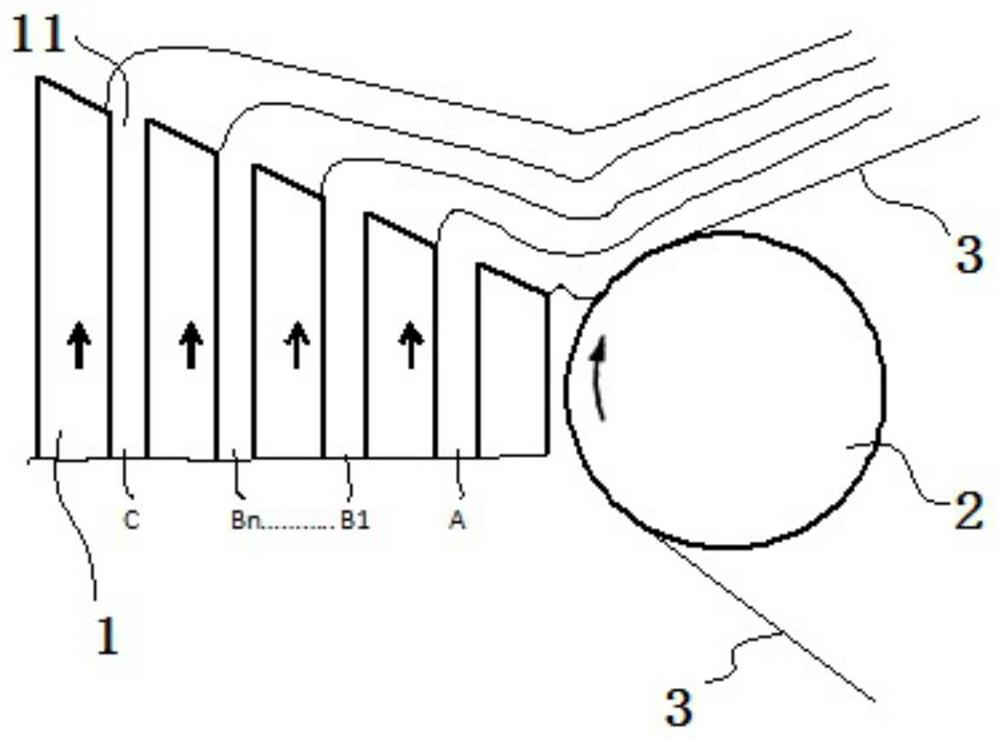
Image

Examples
Embodiment 1
[0030] The B slurry in Example 1 and Example 2 was used to prepare the positive electrode sheet, and the B slurry in Example 3 and Example 4 was used to prepare the negative electrode sheet.
[0031] C slurry includes PVDF, second solvent. The second solvent may be a compound having a relatively strong dipole moment, such as dimethylformamide, dimethylsulfoxide, dimethylacetate, acetone, and N-methyl-2-pyrrolidone (NMP). In particular, NMP is preferred since a large amount of γ-phase crystalline compounds can be obtained using NMP. The mass ratio of PVDF to the second solvent is 1:0.1-100. If the ratio of the second solvent is less than 0.1, PVDF cannot be sufficiently dissolved and cannot be used as a binder. If the ratio of the second solvent exceeds 100, PVDF dissolves sufficiently, but the solution concentration of the active material is too low, reducing the binding effect.
[0032] The C slurry described in Examples 1-4 is configured by PVDF and NMP at a mass ratio of...
Embodiment 2
[0044] This embodiment provides a method for coating lithium battery pole pieces. The only difference between this embodiment and Embodiment 1 is that in this embodiment, the content of dispersant in A slurry is 1wt%, and the content of graphene flakes is 10wt. %.
Embodiment 3
[0046] This embodiment provides a method for coating a lithium battery pole piece. The method is to prepare a negative pole piece by coating A slurry, B slurry, and C slurry on a copper foil through a multi-layer slide coating process. Where B slurry includes B 1 slurry, B 2 slurry, B 3 slurry. B 1 Coating thickness of slurry, B 2 Coating thickness of slurry, B 3 The coating thicknesses of the pastes were all the same. After the negative electrode sheet prepared in this example is dried, the B layer includes B 1 Layer, B 2 Layer, B 3 Layer, B 1 Layer and A layer are connected, B 3 Layer and C layer are connected.
[0047] B 1 In the slurry, the binder content is 10wt%, the solid content (comprising negative electrode active material and conductive additive) is 50wt%, and the surfactant content is 0.1wt%, B 2 In the slurry, the binder content is 9.9wt%, the solid content is 49wt%, and the surfactant content is 0.2wt%, B 3 The binder content in the slurry is 9.8wt%...
PUM
| Property | Measurement | Unit |
|---|---|---|
| thickness | aaaaa | aaaaa |
| thickness | aaaaa | aaaaa |
Abstract
Description
Claims
Application Information