System for removing SO3 in desulfurization wastewater and flue gas based on high and low temperature flue cascade evaporation

A desulfurization wastewater, high and low temperature technology, applied in the direction of water/sewage treatment, water/sludge/sewage treatment, gaseous effluent wastewater treatment, etc., can solve the problem of limiting the consumption of desulfurization wastewater, reducing the service life of equipment, and changing the volume of wastewater. To reduce the risk of sticking or even "blocking" the air preheater and improve the consumption capacity

Active Publication Date: 2021-04-23
武汉天空蓝环保科技有限公司
View PDF13 Cites 0 Cited by
  • Summary
  • Abstract
  • Description
  • Claims
  • Application Information

AI Technical Summary

Problems solved by technology

[0003] (1) High content of Cl - It is easy to cause corrosion to the flue and subsequent equipment and reduce the life of the equipment;
[0004] (2) The evaporation area of ​​the flue is limited: the desulfurization wastewater is atomized and sprayed into the flue, and the volume content of water vapor in the flue gas after evaporation is relatively increased, increasing the SO in the flue gas 3 When the flue temperature is low (generally lower than 147°C), the risk of forming highly viscous ABS (ammonia bisulfate) can only be implemented in the flue behind the air preheater (ABS will block the low temperature end of the air preheater)
[0005] (3) Since the flue gas temperature behind the air preheater is low (normally about 120°C), the consumption of desulfurization wastewater is limited, and it is often necessary to carry out "reduction" treatment in the early stage, and the investment is high;
[0006] (4) Affected by boiler load, flue gas volume, and flue layout conditions, the amount of waste water that can be digested varies greatly. When the complex load is too low, it cannot even evaporate at all.

Method used


Image

  • System for removing SO3 in desulfurization wastewater and flue gas based on high and low temperature flue cascade evaporation
  • System for removing SO3 in desulfurization wastewater and flue gas based on high and low temperature flue cascade evaporation
  • System for removing SO3 in desulfurization wastewater and flue gas based on high and low temperature flue cascade evaporation

Examples


Embodiment Construction

[0027] The following will clearly and completely describe the technical solutions in the embodiments of the present invention with reference to the accompanying drawings in the embodiments of the present invention. Obviously, the described embodiments are only some, not all, embodiments of the present invention. Based on the embodiments of the present invention, all other embodiments obtained by persons of ordinary skill in the art without making creative efforts belong to the protection scope of the present invention.

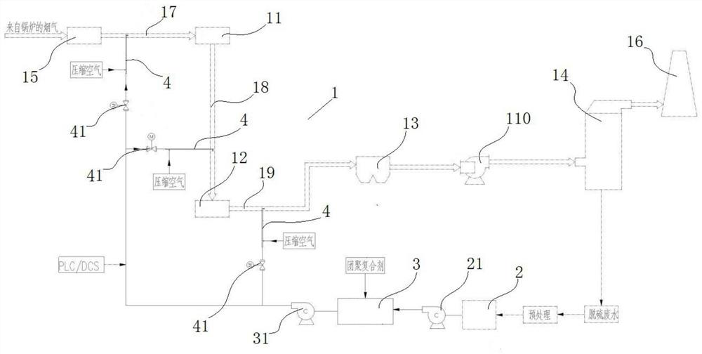
[0028] see figure 1 , the embodiment of the present invention provides a method based on high and low temperature flue cascade evaporation desulfurization wastewater and SO in flue gas 3 The removal system can be used to realize the evaporation consumption of desulfurization wastewater and the SO in flue gas 3 Removal, specifically includes flue 1, on which there is a denitrification device 11, an air preheater 12, a dust collector 13 and a desulfurization to...


PUM


Abstract

The invention provides a system for removing SO3 in desulfurization wastewater and flue gas based on high and low temperature flue cascade evaporation. The system comprises a flue, a denitration device, an air pre-heater, a dust remover and a desulfurization tower are arranged on the flue, an agglomeration composite solution preparation device is further included, desulfurization wastewater generated by the desulfurization tower is treated and then guided into the agglomeration composite solution preparation device, and a liquid outlet of the agglomeration composite solution preparation device is connected with a plurality of spray guns; and a nozzle of at least one spray gun extends into the first flue section, a nozzle of at least one spray gun extends into the second flue section, and a nozzle of at least one spray gun extends into the third flue section. A prepared agglomeration composite solution is sprayed into the first flue section, the second flue section and the third flue section, on one hand, desulfurization wastewater evaporation can be accelerated, the problem of difficult low-temperature evaporation is avoided, on the other hand, temperature gradient removal of SO3 is formed, and the probability of forming ABS through ammonia escape generated by denitration is eliminated from the source.

Description

technical field [0001] The invention relates to energy saving and environmental protection, in particular to a method based on high and low temperature flue cascade evaporation desulfurization wastewater and SO in flue gas 3 Remove the system. Background technique [0002] Desulfurization wastewater has high soluble salt content, Cl - It is highly corrosive and cannot be directly discharged outside. The "zero discharge" treatment of desulfurization wastewater is the direction of desulfurization wastewater treatment. Previously, concentration reduction + evaporative desalination treatment of desulfurization wastewater was mostly used, the investment and operation costs were high, and the "miscellaneous salt" produced was due to Cl - , heavy metals, etc. are high in content and become "hazardous waste", which is still to be processed and difficult to be accepted by users. Most of the flue evaporation systems are now used for evaporation treatment: that is, the temperature o...

Claims


Application Information

Patent Timeline
Patent Type & Authority Applications(China)
IPC IPC(8): F23J15/00B01D53/79B01D53/50B01D53/64C02F9/10C02F103/18C02F101/10C02F101/12C02F101/20
CPCF23J15/003B01D53/79B01D53/507B01D53/64C02F1/58C02F1/62C02F1/048C02F1/12B01D2251/80B01D2258/0283C02F2103/18C02F2101/101C02F2101/12C02F2101/20
Inventor 李湧张军营张润伟张涛周琼琼
Owner 武汉天空蓝环保科技有限公司
Why Eureka
Try Eureka