Pyrolysis gas separation system with cooling capacity recovery function and separation method thereof
A separation system and cold energy recovery technology, used in absorption purification/separation, hydrocarbon purification/separation, chemical instruments and methods, etc., can solve the problems of low investment recovery rate, large investment in cracking gas separation process, and large investment.
- Summary
- Abstract
- Description
- Claims
- Application Information
AI Technical Summary
Problems solved by technology
Method used
Image
Examples
Embodiment 1
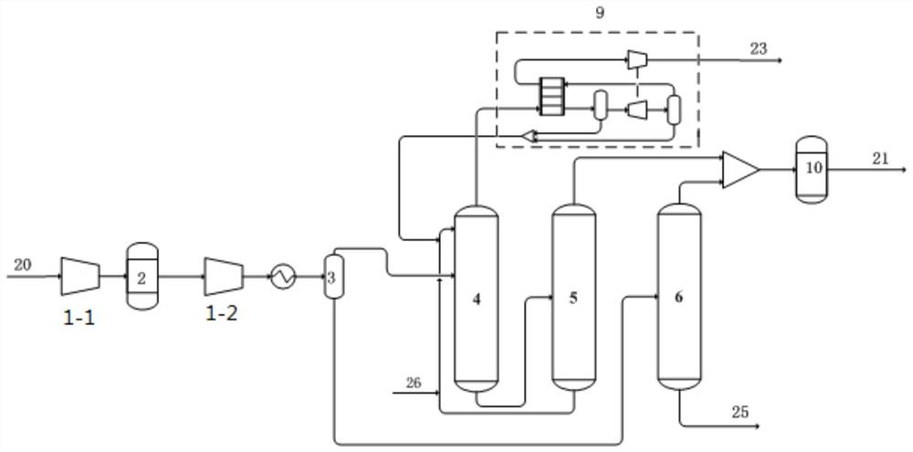
[0071] like figure 1 Shown, a kind of cracking gas separation system comprises: compressor (compressor front section 1-1, compressor compressor rear section 1-2); Purification system 2; Gas-liquid separation tank 3; Absorption tower 4; Desorption tower 5 ; Deweighting tower 6; Carbon two hydrogenation reactor 10; Refrigeration recovery system 9.
[0072] After the compressor section is connected to the purification system 2, it is connected to the rear section 1-2 of the compressor. The outlet of the rear section 1-2 of the compressor is connected to the cooler and then connected to the gas-liquid separation tank 3. The gas phase is connected to the middle of the absorption tower 4, and the liquid phase is connected to the separation tank 3. The middle part of heavy tower 6. The bottom of the absorption tower 4 is connected to the desorption tower 5; the top of the desorption tower 5 is connected to the carbon dioxide hydrogenation reactor 10; the bottom of the tower is conne...
Embodiment 2
[0093] A cracked gas separation system is the same as that of Embodiment 1, the only difference being that this embodiment does not have an absorbent replenishment pipeline.
[0094] The incoming amount of cracked gas is 42000kg / h. Propane was chosen as the absorbent.
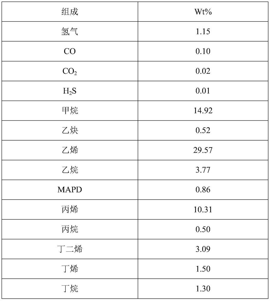
[0095] The steps that the separation method of described a kind of cracking gas comprises are identical with embodiment 1, and cracking gas input composition is also identical.
[0096] The composition of the obtained crude ethylene product is shown in Table 4.
[0097] Table 4 crude ethylene product composition
[0098] composition mol% hydrogen 0.6 methane 15.4 Vinyl 74.9 ethane 8.9 Propylene 0.2
[0099] The mass composition of other streams is shown in Table 5.
[0100] Table 5 Quality composition of different streams
[0101]
[0102]
[0103] In this example, the ethylene recovery rate was 99.0%.
Embodiment 3
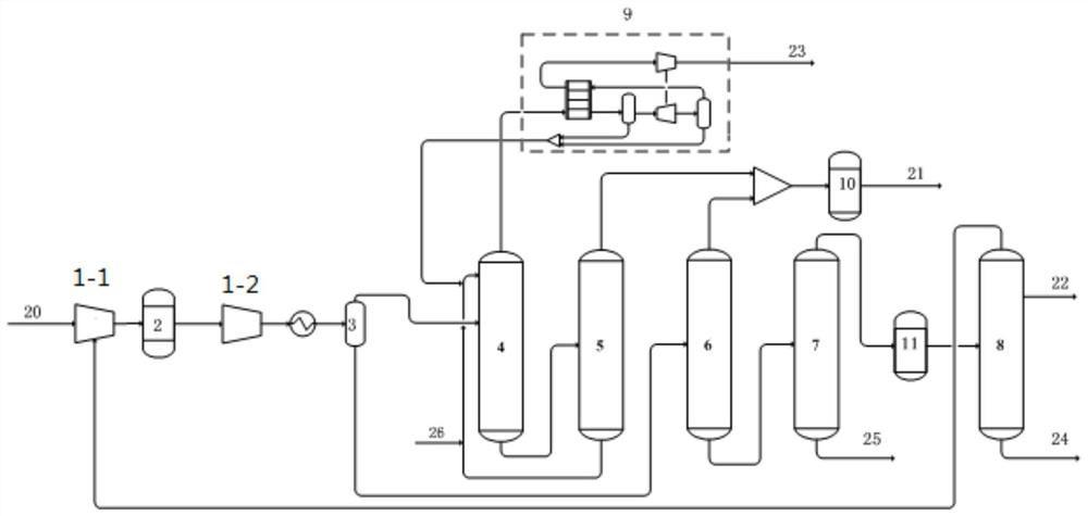
[0105] use as figure 2 A kind of pyrolysis gas separation system shown comprises: compressor (compressor front section 1-1, compressor rear section 1-2); Purification system 2; Gas-liquid separation tank 3; Absorption tower 4; Desorption tower 5; Heavy tower 6; Depropanizer 7; Propylene rectification tower 8; Cooling recovery system 9; C2 hydrogenation reactor 10; C3 hydrogenation reactor 11.
[0106] After the compressor section is connected to the purification system 2, it is connected to the rear section 1-2 of the compressor. The outlet of the rear section 1-2 of the compressor is connected to the cooler and then connected to the gas-liquid separation tank 3. The gas phase is connected to the middle of the absorption tower 4, and the liquid phase is connected to the separation tank 3. The middle part of heavy tower 6. The bottom of the absorption tower 4 is connected to the desorption tower 5; the top of the desorption tower 5 is connected to the carbon dioxide hydrogena...
PUM
 Abstract
Description
Claims
Application Information
 - R&D
- Intellectual Property
- Life Sciences
- Materials
- Tech Scout
- Unparalleled Data Quality
- Higher Quality Content
- 60% Fewer Hallucinations
Browse by: Latest US Patents, China's latest patents, Technical Efficacy Thesaurus, Application Domain, Technology Topic, Popular Technical Reports.
© 2025 PatSnap. All rights reserved.Legal|Privacy policy|Modern Slavery Act Transparency Statement|Sitemap|About US| Contact US: help@patsnap.com


