Welding method for target material and back plates

A welding method and target material technology, applied in the field of target material manufacturing, can solve problems such as target material deformation

Pending Publication Date: 2021-05-04
KONFOONG MATERIALS INTERNATIONAL CO LTD
View PDF10 Cites 3 Cited by
  • Summary
  • Abstract
  • Description
  • Claims
  • Application Information

AI Technical Summary

Problems solved by technology

[0006] Aiming at the problems existing in the prior art, the object of the present invention is to provide a welding method of the target and the back plate, the welding method effectively solves the problem of deformation of the target during the welding process through the design of the welding structure, and at the same time ensures that the welding The bonding rate and welding bonding strength have good industrial application prospects

Method used


Image

  • Welding method for target material and back plates

Examples


Embodiment 1

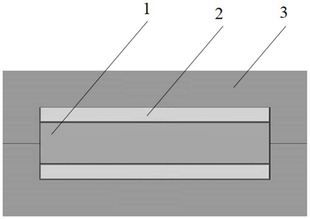
[0063] This embodiment provides a welding structure of the target and the back plate, the welding structure is as follows figure 1 shown.

[0064] The welding structure includes a target 1, an intermediate layer 2 and a back plate 3;

[0065] The target material 1 is located between two intermediate layers 2 , and two backplanes 3 are arranged symmetrically on the outside of the two intermediate layers 2 to wrap the target material 1 and the intermediate layer 2 .

Embodiment 2

[0067] This embodiment provides a method for welding a target and a back plate, and the welding structure of the target and the back plate refers to the welding structure in Embodiment 1.

[0068] Described welding method comprises the following steps:

[0069] (1) Polish the welding surface of the titanium-aluminum alloy target and the aluminum back plate, and the two surfaces of the aluminum alloy interlayer in contact with the aluminum back plate and the titanium-aluminum alloy target, and then use isopropanol for ultrasonic cleaning , after cleaning for 5 minutes, carry out vacuum drying at 90°C for 60 minutes; assemble the dried titanium-aluminum alloy target material with a thickness of 5 mm, an aluminum alloy intermediate layer with a thickness of 1 mm, and an aluminum back plate to obtain an assembly assembly;

[0070] (2) The assembled components obtained in step (1) are sheathed and welded, then degassed at 100°C for 2 hours, then hot isostatic pressed at 200°C and 5...

Embodiment 3

[0072] This embodiment provides a method for welding a target and a back plate, and the welding structure of the target and the back plate refers to the welding structure in Embodiment 1.

[0073] Described welding method comprises the following steps:

[0074] (1) Polish the contact surface between the titanium-aluminum alloy target and the aluminum alloy back plate, as well as the two surfaces of the aluminum alloy intermediate layer in contact with the aluminum alloy back plate and the titanium-aluminum alloy target, and then use isopropanol to Ultrasonic cleaning, after cleaning for 120 minutes, vacuum drying at 120°C for 40 minutes; assemble the dried titanium-aluminum alloy target material with a thickness of 20 mm, the aluminum alloy intermediate layer with a thickness of 7 mm, and the aluminum alloy back plate to obtain an assembly assembly ;

[0075] (2) The assembled components obtained in step (1) are sheathed and welded, then degassed at 400°C for 20 hours, then h...


PUM

PropertyMeasurementUnit
thicknessaaaaaaaaaa
thicknessaaaaaaaaaa

Abstract

The invention provides a welding method for a target material and back plates. The welding method comprises the steps of assembling the target material, middle layers and the back plates to obtain an assembly; enabling the target material to be located between the two middle layers, enabling the two back plates to be symmetrically arranged on the outer sides of the two middle layers, and wrapping the target material and the two middle layers; and carrying out sheath welding, degassing and hot isostatic pressing on the obtained assembly, and then stripping the back plate on one side of the sputtering face of the target material of the assembly and the middle layers to obtain a target material assembly. According to the welding method, through the design of a welding structure, the problem of target material deformation in the welding process is effectively solved, meanwhile, the welding bonding rate and the welding bonding strength are guaranteed, and good industrial application prospects are achieved.

Description

technical field [0001] The invention belongs to the technical field of target material manufacturing, and in particular relates to a welding method for a target material and a back plate. Background technique [0002] As the preparation of semiconductor integrated circuit chips develops toward larger dimensions, the size of the sputtering target and the sputtering power also increase accordingly. The requirements for the microstructure of the sputtering target and the connection between the target and the backplane are also getting higher and higher. The connection technology of large-area targets and backplanes has become a key technology in the preparation of target components. In the sputtering process, the target assembly, as the cathode, should first have excellent electrical conductivity. At the same time, in order to discharge the heat generated by high-energy ions bombarding the surface of the target at high speed, the target assembly should also have excellent ther...

Claims


Application Information

Patent Timeline
Patent Type & Authority Applications(China)
IPC IPC(8): B23K20/02B23K20/22B23K20/24
CPCB23K20/021B23K20/026B23K20/24B23K20/22
Inventor 姚力军边逸军潘杰王学泽江胜君
Owner KONFOONG MATERIALS INTERNATIONAL CO LTD
Why Eureka
Try Eureka