Solar slurry stirring device

A stirring device and solar energy technology, which is applied to mixers with rotating stirring devices, mixer accessories, conductive materials dispersed in non-conductive inorganic materials, etc., can solve problems such as low stirring efficiency, complex structure, and slow stirring speed. Achieve the effect of improving the uniformity of stirring, the overall structure is simple, and the effect of eliminating dead corners of stirring

Inactive Publication Date: 2021-05-07
JIANGSU ZHENGNENG ELECTRONICS TECH CO LTD
View PDF8 Cites 2 Cited by
  • Summary
  • Abstract
  • Description
  • Claims
  • Application Information

AI Technical Summary

Problems solved by technology

[0002] Solar electronic paste usually refers to the back silver paste, back aluminum paste and front silver paste for crystalline silicon solar cells. It is a viscous mechanical mixture composed of powder, adhesive, solvent and additives. The slurry is used in the photovoltaic industry; in the solar electronic slurry manufacturing process, a stirring process is required; the stirring equipment in the prior art has low stirring efficiency during the stirring process, and there is sedimentation and dry powder in the vertical dead corner of the side wall, and the stirring effect Bad, uneven dispersion of raw materials and other problems;
[0003] In order to overcome the above defects, a patented stirring device for solar cell sheet printing paste (publication number: CN209271311U) solves the technical problems such as the structure of the existing stirrer is too simple, it is impossible to quickly stir all kinds of raw materials evenly, and the stirring speed is slow. It includes a base, a stirring box is fixed on the base, the upper part of the mixing box has a material inlet, a solenoid valve 1 is arranged at the inlet, the lower part of the mixing box has a discharge port, and a solenoid valve 2 is installed at the discharge port, and the base is fixed. There is a column, and the lifting seat is arranged on the column, and the lifting seat is located directly above the mixing box, the lifting seat is connected with the upper end of the linkage rod, and the lower end of the linkage rod extends into the mixing box and is connected with the positioning frame, and the positioning frame is provided with a stirring mechanism. The lifting seat is also connected with a driving structure that can make it move up and down, so that it has the advantage of fast stirring, but also because of the additional sets of driving parts, the overall equipment cost is high and the structure is relatively complicated

Method used


Image

  • Solar slurry stirring device
  • Solar slurry stirring device
  • Solar slurry stirring device

Examples


Embodiment 1

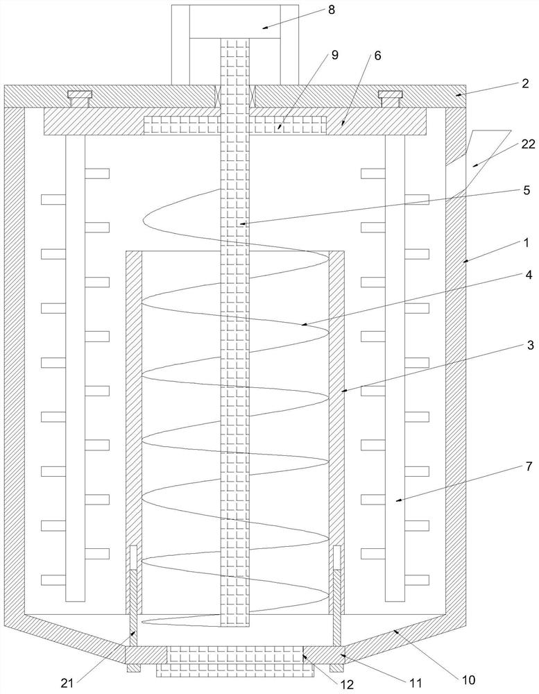
[0028] Such as figure 1 A stirring device for solar slurry shown in this embodiment includes a mixing tank 1, a barrel cover 2, a spiral riser pipe 3, a spiral lift blade 4, a central shaft 5, a rotating disc 6, a stirring rod 7, a stirring Motor 8 and driving block 9; The side wall of mixing bucket 1 is provided with feed inlet 22; The discharge opening 12 places are connected with sealing plug; The bottom of mixing bucket 1 is provided with tapered sliding surface 10, and the bottom of The bottom end is provided with a platform surface 11, the middle part of the platform surface 11 is provided with a discharge port 12, and the top of the discharge port 12 is provided with a spiral riser pipe 3, and the bottom end of the spiral riser pipe 3 is fixed on the platform surface 11 by an adjustment rod 21; The spiral riser 3 is provided with a central axis 5, and the spiral lifter blade 4 is fixed outside the central axis 5. The spiral lifter blade 4 is used to lift the solar slurr...

Embodiment 2

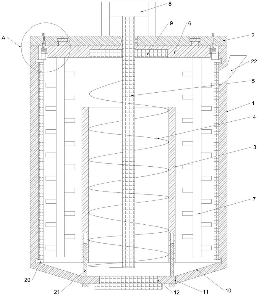
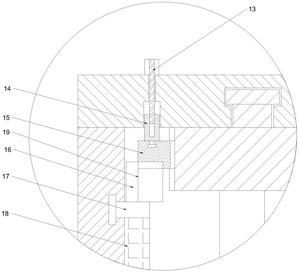
[0030] combine Figure 2 to Figure 3 The stirring device for solar slurry shown in this embodiment is different from Embodiment 1 in that it also includes a push rod 13, a top plate 14, a matching block 15, a drive plate 16, and a first swivel ring 17. The second swivel 20 and the scraper 18; at least one set of mating block 15 is provided, and is longitudinally slidably connected to the periphery of the rotating disk 6, and the top side of the mating block 15 is provided with an arc-shaped chute connected to the top disk 14 in rotation , and the top of the top plate 14 is provided with a threaded notch, the internal thread of the threaded notch is connected with a push rod 13, and the top of the push rod 13 passing through the bung 2 is also provided with a limit block; The matching block 15 is inserted into the matching groove 19, the bottom end of the drive plate 16 is fixed with a first swivel 17, and the bottom side of the first swivel 17 is provided with at least one set...


PUM


Abstract

The invention provides a solar slurry stirring device. The solar slurry stirring device comprises a stirring barrel, a barrel cover, a spiral lifting pipe, a spiral lifting blade, a central shaft, a rotating disc, a stirring rod, a stirring motor and a driving block, a conical sliding surface is arranged at the bottom of the stirring barrel, a platform surface is arranged at the bottom end of the conical sliding surface, a discharging opening is formed in the middle of the platform surface, a spiral lifting pipe is arranged above the discharging opening, the central shaft is arranged in the spiral lifting pipe, the spiral lifting blade is fixed outside the central shaft, and the top end of the central shaft penetrates out of the barrel cover and is in driving connection with the stirring motor; at least one group of driving blocks are further fixed outside the central shaft, the top end of the rotating disc is rotationally connected to the barrel cover, driving notches used for being matched with the driving blocks in an inserted mode are further formed in the bottom side of the rotating disc, and at least one group of stirring rods located between the spiral lifting pipe and the stirring barrel are further fixed to the bottom side of the rotating disc. The stirring cost is low, the stirring uniformity is better, and precipitated dry powder at dead angles can be better eliminated so that the stirring effect is better.

Description

technical field [0001] The invention relates to a stirring device, in particular to a stirring device for solar slurry. Background technique [0002] Solar electronic paste usually refers to the back silver paste, back aluminum paste and front silver paste for crystalline silicon solar cells. It is a viscous mechanical mixture composed of powder, adhesive, solvent and additives. The slurry is used in the photovoltaic industry; in the solar electronic slurry manufacturing process, a stirring process is required; the stirring equipment in the prior art has low stirring efficiency during the stirring process, and there is sedimentation and dry powder in the vertical dead corner of the side wall, and the stirring effect Bad, uneven dispersion of raw materials and other problems; [0003] In order to overcome the above defects, a patented stirring device for solar cell sheet printing paste (publication number: CN209271311U) solves the technical problems such as the structure of ...

Claims


Application Information

Patent Timeline
Patent Type & Authority Applications(China)
IPC IPC(8): B01F15/00B01F7/16B01F7/18B01F7/24B01F5/10H01B1/22H01L31/0224
CPCH01B1/22H01L31/0224B01F25/52B01F25/54B01F27/85B01F27/92B01F27/90B01F35/123B01F35/3231
Inventor 黄奉康张群冷青松耿心彤李鹏赵军
Owner JIANGSU ZHENGNENG ELECTRONICS TECH CO LTD
Why Eureka
Try Eureka