Oil-gas separation and recovery device and method thereof

A technology of oil gas and separation tower, which is applied in the fields of oil refining and chemical industry, and can solve the problems of high material requirements, long gasoline process, and large heat load of reboiler at the bottom of the tower.

Active Publication Date: 2021-05-07
SINOPEC ENG +1
View PDF5 Cites 1 Cited by
  • Summary
  • Abstract
  • Description
  • Claims
  • Application Information

AI Technical Summary

Problems solved by technology

[0006] (2) Gasoline circulates between the gasoline absorption tower, the desorption tower and the stabilization tower, the temperature at the bottom of the ethane desorption tower and the stabilization tower is relatively high, the heat load of the reboiler at the bottom of the tower is large, and the energy consumption is relatively high
[0007] (3

Method used


Image

  • Oil-gas separation and recovery device and method thereof
  • Oil-gas separation and recovery device and method thereof
  • Oil-gas separation and recovery device and method thereof

Examples


Embodiment 1

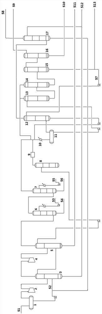
[0069] An oil and gas separation and recovery device includes: oil and gas feed pipeline, gas-liquid separation tank 1, compressor I 2, light and heavy gasoline separation tower 3, compressor II 4, light hydrocarbon-light gasoline separation tower 5, rich gas desulfurization tower 6, Gas-rich alkali washing tower 7, liquid hydrocarbon desulfurization tower 8, liquid hydrocarbon sweetening reactor 9, cooler 10, feed tank 11, absorption tower 12, demethanizer 13, deethanizer 14, depropanizer 15, Propylene rectification tower 16 and absorbent recovery tower 17;

[0070] Among them, the oil and gas feed line is connected to the inlet of the gas-liquid separation tank 1, the top of the gas-liquid separation tank 1 is connected to the compressor I2 and the light and heavy gasoline separation tower 3 in sequence, and the bottom of the tank is connected to the light and heavy gasoline separation tower 3;

[0071] The top of the light and heavy gasoline separation tower 3 is equipped w...

Embodiment 2

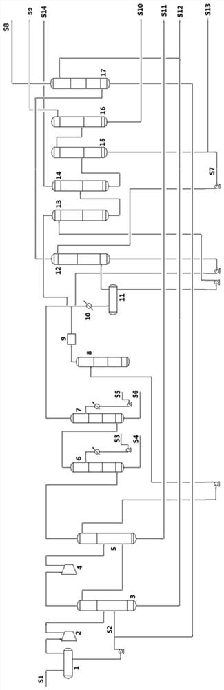
[0104] Separation process such as figure 2 As shown, the only difference with embodiment 1 is:

[0105] (10) Deethanization: The liquid phase from the bottom of the deethanizer 13 is further separated from the C2 component in the deethanizer 14, and the separated mixed C2 component is extracted from the top of the deethanizer 14, and the by-product The carbon dioxide product S14 is obtained, and the liquid phase components above C3 and C3 at the bottom of the tower are sent to the depropanizer 15.

[0106] The light hydrocarbons in the catalytic cracking reaction are separated by the above method, and the composition and properties of the separated products are shown in Table 5 and Table 6.

[0107] table 5

[0108]

[0109]

[0110] Table 6 Properties of gasoline products

[0111] project gasoline Flow rate, kg / h 64252 Density, 20°C 0.742 Distillation percentage, v% En-style distillation (D-86), ℃ 0 44 10 57 30 89 50...


PUM

PropertyMeasurementUnit
Do itaaaaaaaaaa

Abstract

The invention belongs to the field of petrochemical engineering, and particularly discloses an oil-gas separation and recovery device and a method thereof. According to the oil-gas separation and recovery device and the method thereof, gasoline and C4 and below components are separated in advance before light hydrocarbon separation, so that in the follow-up process, gasoline does not need to be adopted for absorbing liquefied gas components, consumption of absorbent circulation is saved, and meanwhile, the tower top material flow of a light hydrocarbon-light gasoline separation tower is desulfurized, so that the material flow does not contain H2S in the light hydrocarbon separation process, the material requirement of a light hydrocarbon separation and recovery system is reduced, the risk possibly caused by H2S leakage is reduced, and the safety of the whole process is ensured; meanwhile, the method is simple in technological process, mild in operation condition and low in energy consumption.

Description

technical field [0001] The invention belongs to the field of oil refining and chemical industry, and more specifically relates to a device and method for oil and gas separation and recovery, and more specifically relates to oil and gas separation and recovery in processes with high gas yields such as catalytic cracking, catalytic cracking and delayed coking. Apparatus and method for recovery. Background technique [0002] Light hydrocarbons refer to components such as methane, ethane, ethylene, propane, propylene, and C4 obtained from petrochemical processes. The separation process of light hydrocarbons has always been the focus of petrochemical processes. Existing catalytic cracking, hydrocracking, and delayed coking processes with high gas yields often use absorption stabilization to recover liquefied gas (C3 / C4) components to achieve liquefied gas components and dry gas (H 2 / C1 / C2) component separation, while stabilizing gasoline to ensure that the vapor pressure of gas...

Claims


Application Information

Patent Timeline
IPC IPC(8): C10G53/02
CPCC10G53/02
Inventor 黄孟旗江盛阳段丹吴雷余龙红丁昱文
Owner SINOPEC ENG
Why Eureka
Try Eureka