
System for reducing industrial sludge and improving sludge dewatering performance and industrial sludge treatment method

A technology for industrial sludge and sludge dewatering, applied in water/sludge/sewage treatment, dehydration/drying/concentrated sludge treatment, sludge treatment, etc. secondary pollution and other problems, to achieve the effect of saving sludge dewatering operation costs, compact system structure, and saving disposal costs

Active Publication Date: 2021-05-11
上海爱丽更环境科技有限公司
View PDF5 Cites 0 Cited by
  • Summary
  • Abstract
  • Description
  • Claims
  • Application Information

AI Technical Summary

Problems solved by technology

[0004]Current sludge reduction technologies mainly include chemical, physical and biological methods. Traditional physical methods have high energy consumption, low economic benefits and high equipment requirements Shortcomings
The biological method has disadvantages such as long time for microbial domestication, difficulty in strain screening, high cost of enzymes, and easy to produce secondary pollution, etc., making it difficult to popularize and use in engineering, while chemical methods can better solve these problems
Chemical methods mainly include ozone oxidation, chlorine oxidation, Fenton oxidation, and hot alkali method, among which, the ozone oxidation method needs to be equipped with an ozone generator because of the characteristics of ozone needs to be produced and used immediately, and the equipment investment is large, while the chlorine oxidation method will generate three Chloromethane and other carcinogens lead to poor effluent quality and affect the normal operation of biochemical systems
Fenton oxidation and hot alkali method have problems such as unstable reduction effect

Method used


Image

  • System for reducing industrial sludge and improving sludge dewatering performance and industrial sludge treatment method
  • System for reducing industrial sludge and improving sludge dewatering performance and industrial sludge treatment method
  • System for reducing industrial sludge and improving sludge dewatering performance and industrial sludge treatment method

Examples


Embodiment 1

[0121] Using the system for reducing the amount of industrial sludge and improving the dewatering performance of sludge of the present invention to treat the physical, chemical and biochemical mixed industrial sludge with a solid content of 2% in a chemical plant in Nantong includes the following steps:

[0122] S1, putting the industrial sludge with a solid content of 2% into the sludge thickener 1 to increase the solid content of the industrial sludge to 4%.

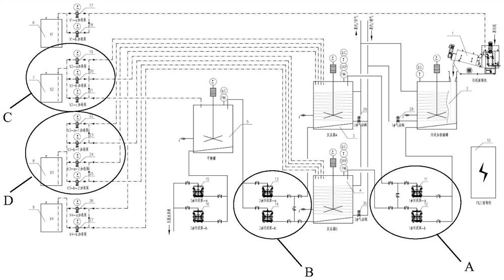
[0123] S2, transfer the concentrated industrial sludge with a solid content of 4% to the sludge heating storage tank 2, when the concentrated industrial sludge in the sludge heating storage tank 2 reaches the low level set by the first liquid level gauge , start the first stirring device to stir at a speed of 50rpm, and the stirring time is 60min. Simultaneously start the first pneumatic valve 28 so that steam enters the first steam jacket heating system to heat the concentrated industrial sludge to 60°C.

[0124] Whe...

Embodiment 2

[0141] The method of embodiment 2 is identical with embodiment 1, and its difference is only in:

[0142] (1) In step S1, the solid content of the industrial sludge is increased to 5%.

[0143] (2) In step S2, the stirring speed is 70 rpm, the stirring time is 50 min, and the concentrated industrial sludge is heated to 70°C.

[0144] (3) In step S3, in the first reactor 3, dosing concentration is the sulfuric acid of 35wt%, and stirring speed is 70rpm, and industrial sludge insulation is 70 ℃, and pH is 2.2; The concentration of hydrogen peroxide is 31wt%, hydrogen peroxide The dosing quality is 0.08g / g industrial sludge dry weight, the dosing time of hydrogen peroxide is 75min, and the dosing rate of the hydrogen peroxide dosing pump is 2.08L / h.

[0145] (4) In step S4, in the first reactor 3, dosing concentration is the sodium hydroxide of 35wt%, and stirring speed is 70rpm, and industrial sludge insulation is 70 ℃; pH is 10.5, and the concentration of hydrogen peroxide is ...

Embodiment 3

[0149] The method of embodiment 3 is identical with embodiment 1, and its difference is only in:

[0150] (1) In step S1, the solid content of the industrial sludge is increased to 8%.

[0151] (2) In step S2, the stirring speed is 80 rpm, the stirring time is 40 min, and the concentrated industrial sludge is heated to 80°C.

[0152] (3) In step S3, in the first reactor 3, dosing concentration is the sulfuric acid of 45wt%, and stirring speed is 80rpm, and industrial sludge insulation is 80 ℃, and pH is 2.4; The concentration of hydrogen peroxide is 32wt%, hydrogen peroxide The dosing quality is 0.09g / g industrial sludge dry weight, the dosing time of hydrogen peroxide is 80min, and the dosing rate of the hydrogen peroxide dosing pump is 3.51L / h.

[0153] (4) In step S4, in the first reactor 3, dosing concentration is the sodium hydroxide of 45wt%, and stirring speed is 80rpm, and industrial sludge insulation is 80 ℃; pH is 11.0, and the concentration of hydrogen peroxide is ...


PUM

PropertyMeasurementUnit
areaaaaaaaaaaa

Abstract

The invention provides a system for reducing industrial sludge and improving sludge dewatering performance. The system comprises a sludge thickener, a sludge heating storage tank, a first reactor, a second reactor, a balance tank, a first medicine storage tank, a second medicine storage tank, a third medicine storage tank and a fourth medicine storage tank. The invention also provides a method for treating industrial sludge by using the system for reducing the industrial sludge and improving the sludge dewatering performance. According to the system for reducing the industrial sludge and improving the sludge dewatering performance, sequencing batch alternate reaction of the industrial sludge can be achieved, the sludge reduction is efficiently and stably achieved by 40-70%, the water content can be rapidly reduced to 60% or below after the treated industrial sludge is dewatered through a dewatering system, the system is compact in structure and easy to install, full-automatic operation of the system can be achieved, the operation is simple and convenient, and more sludge outsourcing disposal cost and sludge dewatering operation cost of production enterprises can be saved.

Description

technical field [0001] The invention belongs to the field of industrial sludge treatment, and in particular relates to a system for reducing the amount of industrial sludge and improving the performance of sludge dewatering, and relates to the use of the above-mentioned system for reducing the amount of industrial sludge and improving the performance of sludge dewatering for industrial treatment. sludge method. Background technique [0002] With the development of my country's industrialization, the amount of industrial wastewater treatment is increasing, and the resulting industrial sludge discharge is also increasing. According to the "National Hazardous Waste List", most industrial sludge is hazardous waste. Disposal costs are expensive, which brings a huge economic burden to the production enterprises. In addition, according to laws and regulations such as the "Environmental Protection Law of the People's Republic of China", "Law of the People's Republic of China on the ...

Claims


Application Information

Patent Timeline
Patent Type & Authority Applications(China)
IPC IPC(8): C02F11/147C02F11/13C02F11/00C02F11/06
CPCC02F11/147C02F11/13C02F11/00C02F11/06
Inventor 卢琛梁锐振林伯儒石建华曹宗然吴广汪聪
Owner 上海爱丽更环境科技有限公司
Learn More