
Air-entrained concrete defoaming pouring device

An air-entrained concrete and pouring head technology, which is applied to clay preparation devices, supply devices, cement mixing devices, etc., can solve the problems of reducing flow, difficulty in demoulding, and reducing the amount of end face removal, so as to reduce flow, reduce splashing, The effect of reducing the content of air bubbles

Active Publication Date: 2022-05-27
绵阳优丰磊德新型建材有限公司
View PDF21 Cites 0 Cited by
  • Summary
  • Abstract
  • Description
  • Claims
  • Application Information

AI Technical Summary

Problems solved by technology

[0005] The purpose of the present invention is to address the deficiencies of the prior art, to provide an air-entrained concrete defoaming pouring device, which starts pouring the slurry along the bottom of the mold, and gradually raises the pouring system, effectively reducing the risk of air bubbles being mixed into the slurry during the falling process ; During the lifting process of the pouring system, under the action of the connecting rod, the first pouring head and the second pouring head are gradually opened, so that the slurry pouring process reduces the flow and prevents the risk of air bubbles mixed in the slurry flow process; wherein the present invention has three The pouring efficiency of the pouring port is high; in addition, pouring starts from the bottom of the mold, and the pouring system is gradually improved to reduce the splashing of the slurry during the pouring process, causing the side wall of the mold to be stained with slurry in advance, which solves the problem caused by different mold entry times. Difficult technical problems in the final demoulding. The present invention is easy to demould, and there is no sticky material falling off on the side; through the rolling system, the surface of the poured slurry is defoamed and the upper end surface is rolled to make the air bubbles on the surface of the slurry Completely remove and roll the end face to reduce the amount of end face removal and improve the yield of pouring slurry

Method used


Image

  • Air-entrained concrete defoaming pouring device
  • Air-entrained concrete defoaming pouring device
  • Air-entrained concrete defoaming pouring device

Examples


Embodiment 1

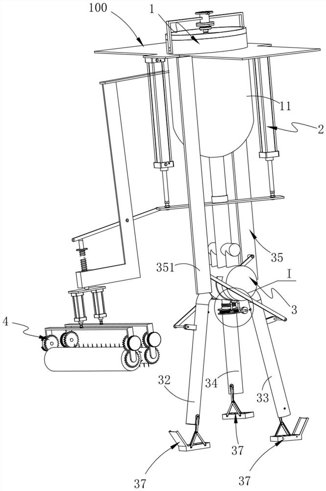
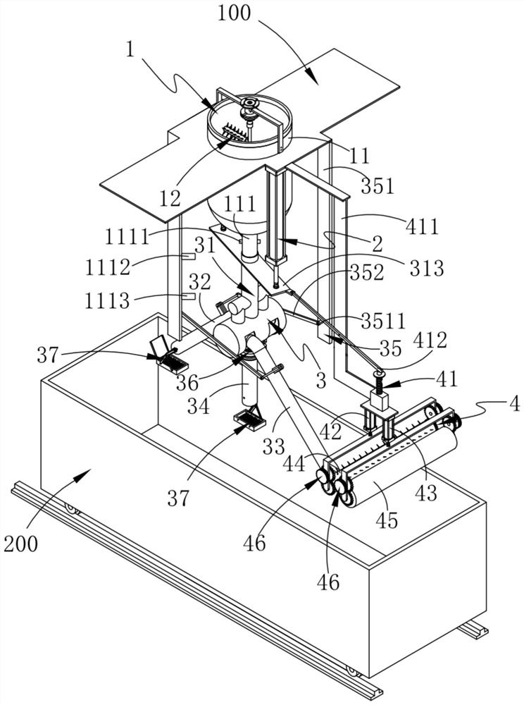
[0069] like Figure 1-2 As shown, an air-entrained concrete defoaming pouring device includes:

[0070] Stirring system 1, the stirring system 1 is installed on the equipment platform 100; in order to facilitate pouring, the equipment platform 100 is generally an upper work surface designed on the upper and lower sides;

[0071] Power system 2, the power system 2 is located on both sides of the stirring system 1, the top of which is connected to the equipment platform 100, and the power system 2 is preferably hydraulically driven to ensure the stability of its up and down movement. You can choose pneumatic transmission or other linear transmission methods;

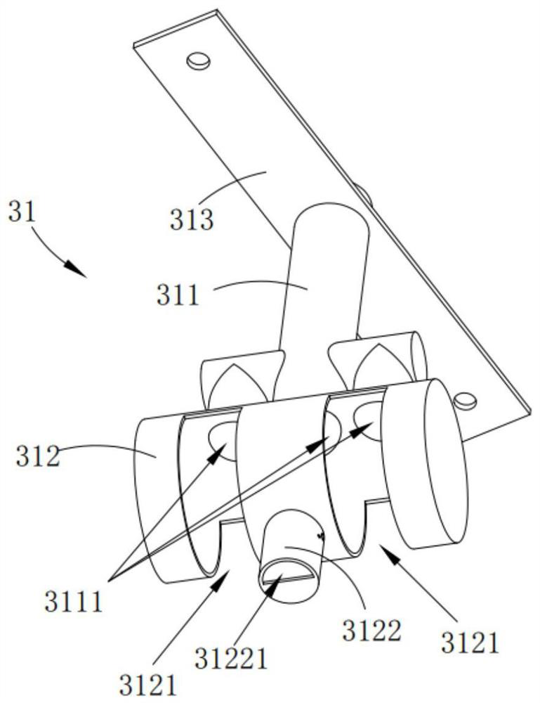
[0072] The pouring system 3, the pouring system 3 is arranged under the stirring system 1 and communicated, and the output end of the power system 2 is connected with the pouring system 3; the pouring system 3 includes a material receiving unit 31, a rotating The first pouring head 32 and the second pouring head 33 dispo...

Embodiment 2

[0104] like Figure 10-12 As shown, the same or corresponding components as those in the first embodiment are given the corresponding reference numerals as in the first embodiment. For the sake of brevity, only the points of difference from the first embodiment are described below. The difference between the second embodiment and the first embodiment is:

[0105] As an improvement, the pouring system 3 further includes an end surface foam breaking unit 37 respectively disposed at the bottom ends of the first pouring head 32 , the second pouring head 33 and the third pouring head 34 , and the end surface foam breaking unit 37 is used for removing Air bubbles in the slurry at the pouring surface.

[0106] as an improvement, such as Figure 10-11 As shown, the end face foam breaking unit 37 includes a power paddle 371 rotatably arranged inside the discharge end of the pouring head, a first drive assembly 372 connected with the power paddle 371, a fixing rod 373 disposed outside...

Embodiment 3

[0114] like Figure 13 As shown, the same or corresponding components as those in the first embodiment are given the corresponding reference numerals as in the first embodiment. For the sake of brevity, only the points of difference from the first embodiment are described below. The difference between the third embodiment and the first embodiment is:

[0115] as an improvement, such as figure 2 , 13 As shown, the stirring system 1 includes a stirring tank 11 connected to the equipment platform 100 and a stirring unit 12 arranged in the stirring tank 11; the stirring unit 12 includes a stirring motor 121 arranged above the stirring tank 11 and The output ends of the stirring motor 121 are axially staggered with a plurality of stirring paddles 122; the stirring paddles 122 are provided with a number of needles 123; the bottom end of the stirring tank 11 is provided with a discharge pipe 111;

[0116] It should be noted that during the stirring process, bubbles will be genera...


PUM


Abstract

The invention provides an air-entrained concrete defoaming pouring device, comprising: a stirring system, a power system, a pouring system, and a rolling system; the rolling system is arranged on one side of the pouring system and is connected to the equipment platform connection; the rolling system includes a transmission unit with one end rotatably connected to one side of the material receiving unit, a drive unit a and a drive unit b connected to the transmission unit, respectively arranged on the drive unit a and drive unit b The two sets of transmission components below and the defoaming rollers and flattening rollers respectively installed on the two sets of transmission components; through the rolling system, the surface of the poured slurry is defoamed and the upper end surface is rolled, so that the air bubbles on the surface of the slurry are completely removed , and carry out rolling leveling on the end face, reduce the amount of end face removal, and improve the yield of casting slurry.

Description

technical field [0001] The invention relates to the technical field of aerated concrete pouring, in particular to a defoaming pouring device for aerated concrete. Background technique [0002] Aerated concrete is a new type of building material, its uniqueness is that it is a very light thermal insulation building wall material. The production process of aerated concrete includes raw material preparation, metering, stirring, pouring, static stop, cutting, pre-curing, steam curing, autoclave mold removal, plate breaking, packaging, etc. Due to the special characteristics of aerated concrete, aerated concrete blocks have become the leading product in the building material industry, and will increasingly show its higher use value and broad development prospects. [0003] Chinese patent CN207077582U discloses an aerated concrete block pouring device, including a frame, a pouring tank a, a pouring tank b, a feeding pipe, an interface, a pouring spout, a bracket, a pouring car, a...

Claims


Application Information

Patent Timeline
Patent Type & Authority Patents(China)
IPC IPC(8): B28B3/12B28B13/02B28C5/16
CPCB28C5/16B28B13/02B28B3/12
Inventor 沈晓鹤麻晓龙
Owner 绵阳优丰磊德新型建材有限公司
Learn More