
Submersible flow electrode capacitive deionization device and method

A technology of capacitive deionization and flow electrode, which is applied in the field of electrosorption, can solve the problems of blockage of water flow cavity and water delivery system, affecting treatment efficiency, and increasing use cost, so as to increase the service life, broaden the application field, and improve the compressive strength. The effect of reducing demand

Pending Publication Date: 2021-05-14
CHONGQING UNIV
View PDF9 Cites 0 Cited by
  • Summary
  • Abstract
  • Description
  • Claims
  • Application Information

AI Technical Summary

Problems solved by technology

However, the water flow cavity of the conventional FCDI device is a sealed structure, which is inconvenient to assemble, which will bring about maintenance and greatly increase the cost of use.
In addition, no matter seawater, brackish water and sewage desalination and metal resource recovery, or ion enrichment and separation in the food and hygiene industries, it is inevitable to face the insoluble matter in the solution, the water flow chamber and the conventional FCDI device The water delivery system faces the risk of clogging, affecting treatment efficiency

Method used


Image

  • Submersible flow electrode capacitive deionization device and method
  • Submersible flow electrode capacitive deionization device and method
  • Submersible flow electrode capacitive deionization device and method

Examples


Embodiment Construction

[0024] Embodiments of the present invention are described in detail below, and examples of the embodiments are shown in the drawings, wherein the same or similar reference numerals represent the same or similar elements or elements having the same or similar functions throughout. The embodiments described below with reference to the accompanying drawings are exemplary, and are only used to describe the specific implementation of the present invention, and should not be construed as limiting the application of the present invention.

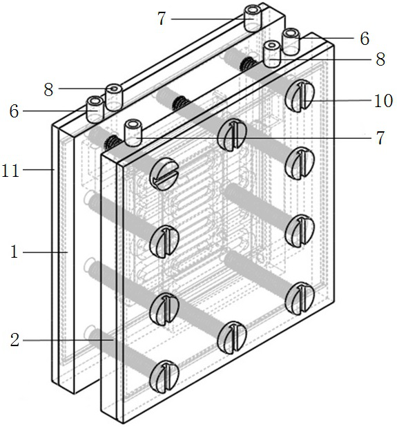
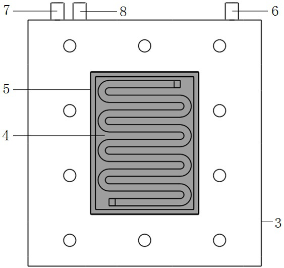
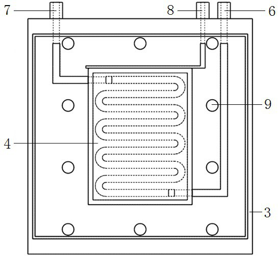
[0025] see Figure 1 to Figure 3 , the submerged flow electrode capacitive deionization device shown includes an electrode module, and the electrode module includes an anode plate 1 and a cathode plate 2 that are oppositely arranged and whose spacing is adjustable. The anode plate 1 and the cathode plate 2 are symmetrical structures. The anode plate 1 includes a housing 3 and a current collector 12. The middle part of the housing 3 is provided wit...


PUM


Abstract

The device comprises an electrode module, and the electrode module comprises an anode plate and a cathode plate; the anode plate and the cathode plate are oppositely arranged, and the distance between the anode plate and the cathode plate is adjustable; each of the anode plate and the cathode plate comprises a shell and a current collector, and the current collectors are embedded in the side faces, close to adjacent polar plates, of the shells; the current collectors in the anode plate and the cathode plate are respectively connected with the positive electrode and the negative electrode of a power supply through wires; an electrode liquid flow channel and an ion exchange membrane tightly covering the electrode liquid flow channel are arranged on the side surface, close to the adjacent polar plates, of the current collector; and an electrode liquid flow inlet and an electrode liquid flow outlet are formed in the shell and the current collector. The device is simple in structure and convenient and fast to assemble, the blocking risk of the device caused by insoluble substances in a solution is effectively avoided, and the later operation and maintenance cost is saved.

Description

technical field [0001] The invention relates to the technical field of electrosorption, in particular to a submerged flow electrode capacitive deionization device and method. Background technique [0002] At present, the main desalination technologies at home and abroad include thermal distillation, chemical method, membrane method and electrochemical method, etc., except for chemical method, they are all physical separation methods. The chemical method is simple and efficient, but it needs to consume a lot of acid, alkali, etc. when regenerating salty sludge, which inevitably causes multi-stage pollution. The thermal distillation method needs to input a large amount of heat energy, its investment and operation costs are high, and its industry adaptability is narrow, so it is not suitable for decentralized and large-scale applications. Pressure-driven membrane filtration methods include nanofiltration, ultrafiltration, reverse osmosis, etc. The effluent quality is better, b...

Claims


Application Information

Patent Timeline
IPC IPC(8): C02F1/469
CPCC02F1/4691C02F1/4604C02F2103/08C02F2103/06C02F2201/46C02F2303/14
Inventor 赵志伟陈瑞邓小永王闯杜锦莹
Owner CHONGQING UNIV
Learn More