
LED power supply

A technology of LED power supply and electrical connection, which is applied in the direction of circuit devices, printed circuits, electrical components, etc., and can solve the problems of large difference between working state and working frequency, increased cost, and reduced electromagnetic compatibility performance.

Pending Publication Date: 2021-05-14
SELF ELECTRONICS CO LTD
View PDF0 Cites 1 Cited by
  • Summary
  • Abstract
  • Description
  • Claims
  • Application Information

AI Technical Summary

Problems solved by technology

[0002] LED power supply is a kind of driving power supply. Miniaturization is the development direction of LED power supply. The miniaturization of LED power supply is more difficult for electromagnetic compatibility design than ordinary power supply, especially for dimmable power supply. There is a big difference between the working state and the working frequency when dimming and light load and low power. The working frequency range of general EMC inductors and capacitors is relatively fixed, and it is difficult to design electromagnetic compatibility (EMC)
[0003] In addition, for compact LED power supplies, in order to solve the heat dissipation problem of power devices, it is generally solved by potting glue, but potting glue has a certain dielectric constant, which reduces the electromagnetic compatibility of the product
Conventional processing method: In order to pass the EMC test standard, add or increase the filter inductance and filter capacitor at the input and output of the circuit, and also increase the distance between the switching power device and the electromagnetic compatibility device to suppress high-frequency electromagnetic , or in the form of a metal shield, the disadvantage of this is that the cost of the product will increase a lot, the complexity of the production process will increase, and the size of the product needs to be increased, it is not easy to make it small, and it cannot meet the market demand

Method used


Image

  • LED power supply
  • LED power supply
  • LED power supply

Examples


Embodiment Construction

[0029] Specific embodiments of the present invention will be described in further detail below based on the accompanying drawings. It should be understood that the description of the embodiments of the present invention here is not intended to limit the protection scope of the present invention.

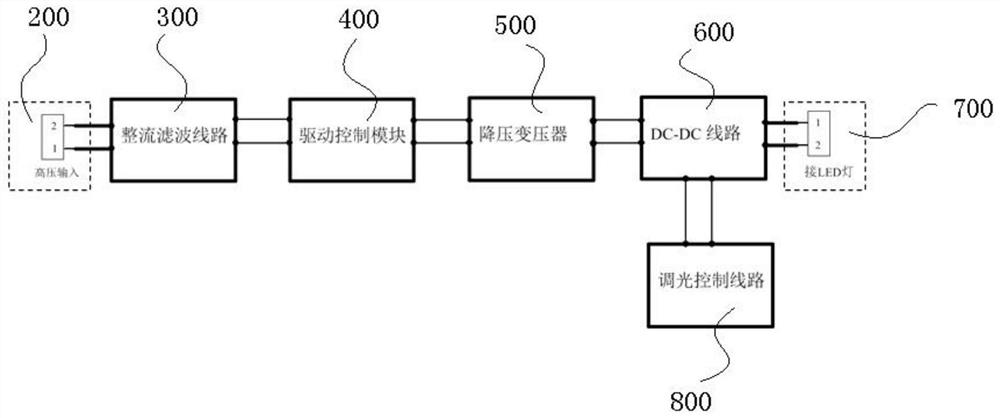
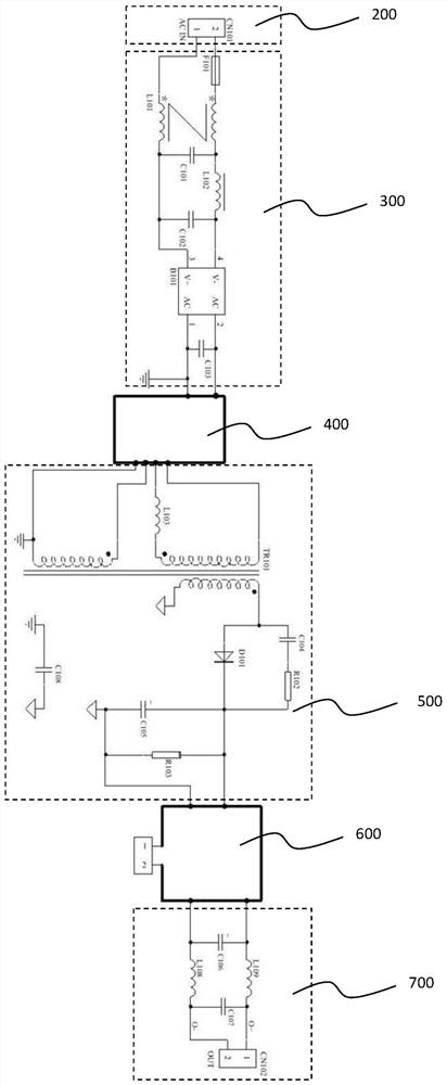
[0030] Such as Figure 1-7 As shown, the LED power supply of this embodiment includes a circuit board assembly 100, and the circuit board assembly 100 is provided with a high voltage input terminal 200, a rectification and filtering circuit 300, a drive control module 400, a step-down transformer 500, a DC- DC line 600 and LED connection terminal 700 . The power supply of the present invention uses a printed circuit board to realize the electrical connection of the electronic components of each module and circuit. How to arrange the above-mentioned modules and circuits on the circuit board is a prior art, and will not be described in detail.

[0031] The LED power supply in the pri...


PUM


Abstract

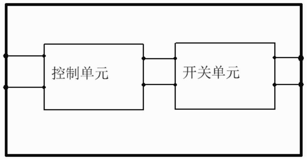
An LED power supply disclosed by the invention comprises a circuit board assembly, wherein the circuit board assembly is provided with a high-voltage input end, a rectification filtering circuit, a driving control module, a step-down transformer, a DC-DC circuit and an LED connection end which are electrically connected in sequence, the driving control module at least comprises a control unit and a switch unit, the circuit board assembly comprises a main board and at least one first daughter board which is electrically connected with the main board and is perpendicular to the main board, and the driving control module is arranged on the first daughter board. According to the LED power supply disclosed by the invention, the circuit board is modularized, the plug board form is adopted, the electronic components are stereoscopically arranged, and the sizes among the components are compact, so that the overall size of a product can be greatly reduced, and the requirement of miniaturization of the product is met.

Description

technical field [0001] The invention relates to the technical field of driving power supply, in particular to an LED power supply. Background technique [0002] LED power supply is a kind of driving power supply. Miniaturization is the development direction of LED power supply. The miniaturization of LED power supply is more difficult for electromagnetic compatibility design than ordinary power supply, especially for dimmable power supply. There is a big difference between the working state and the working frequency of dimming and light load and low power. The working frequency range of general EMC inductors and capacitors is relatively fixed, and the design of electromagnetic compatibility (EMC) is difficult. [0003] In addition, for compact LED power supplies, in order to solve the heat dissipation problem of power devices, glue potting is generally used to solve the problem, but potting glue has a certain dielectric constant, which reduces the electromagnetic compatibili...

Claims


Application Information

Patent Timeline
Patent Type & Authority Applications(China)
IPC IPC(8): H05B45/30H05B45/37H05B45/375H05B45/10
CPCH05B45/30H05B45/37H05B45/375H05B45/10H05K1/141H05K3/366H05K1/0218H05K1/0262H05B45/382H05K9/0022F21V23/006H05B45/36H05K7/14322
Inventor 钱伟书王其明王林吉徐斌杰
Owner SELF ELECTRONICS CO LTD
Learn More