
Harmless treatment device for industrial solid waste

A solid waste, harmless treatment technology, applied in gas treatment, combined devices, incinerators, etc., can solve the problems of low resource utilization, many treatment processes, poor purification effect, etc.

Pending Publication Date: 2021-05-18
信和(天津)环保科技发展有限公司
View PDF6 Cites 1 Cited by
  • Summary
  • Abstract
  • Description
  • Claims
  • Application Information

AI Technical Summary

Problems solved by technology

[0004] The purpose of the present invention is to provide a harmless treatment device for industrial solid waste to solve the above-mentioned background. The efficiency is low, and the current treatment device is not thorough in the treatment of dust and impurities in the flue gas, and the purification effect is poor

Method used


Image

  • Harmless treatment device for industrial solid waste
  • Harmless treatment device for industrial solid waste
  • Harmless treatment device for industrial solid waste

Examples


Embodiment 1

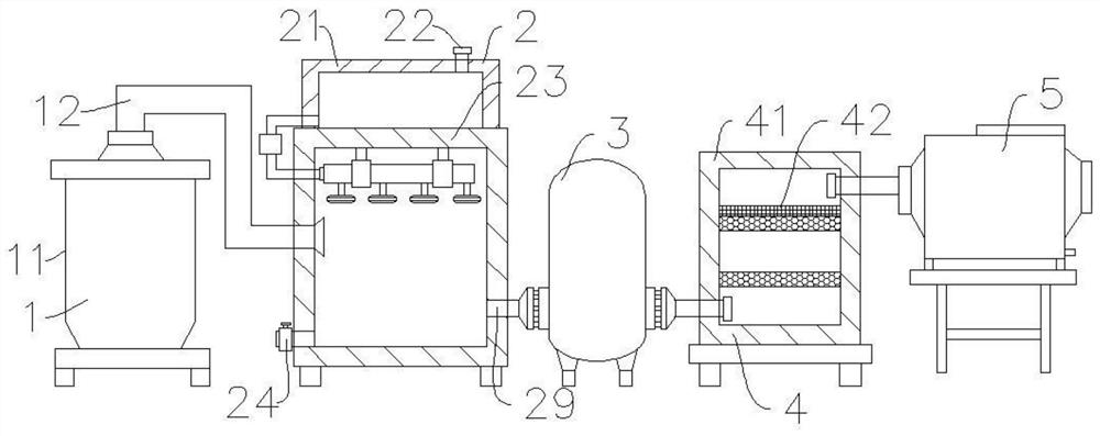
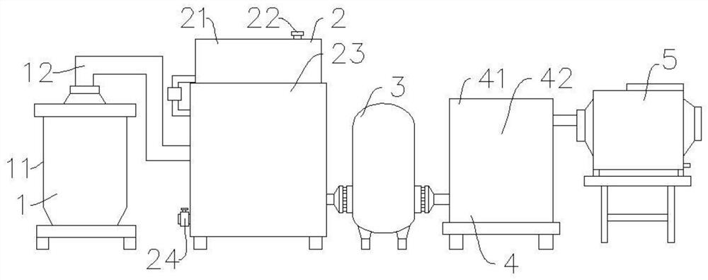
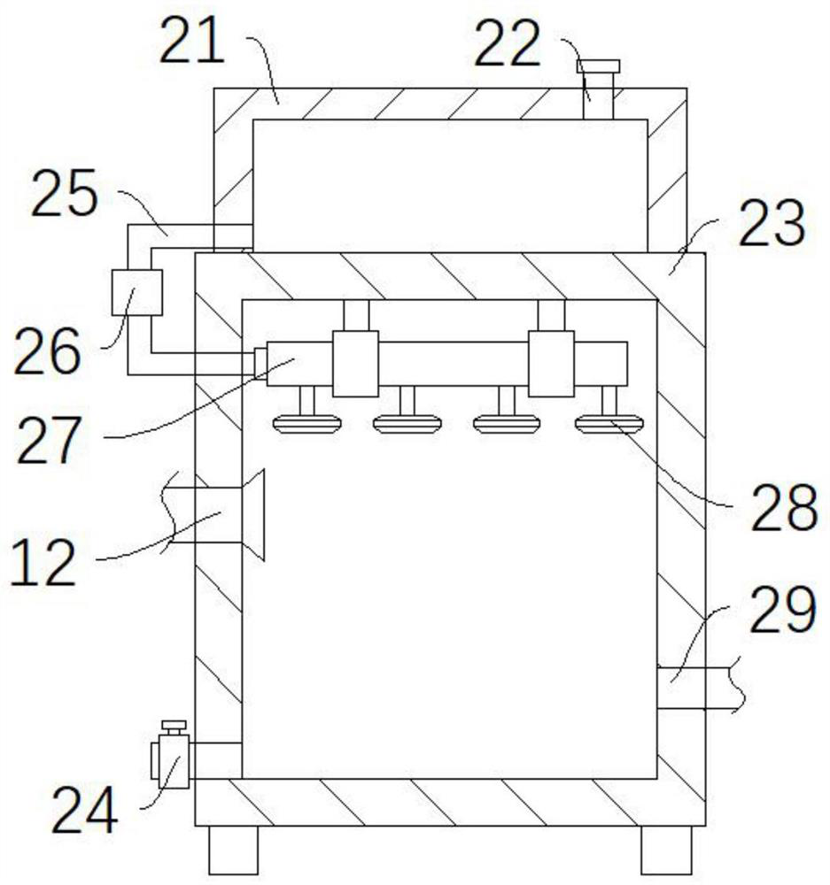
[0032] Such as Figure 1-Figure 8As shown, a harmless treatment device for industrial solid waste of the present invention includes a combustion mechanism 1 for burning solid waste, a heat exchanger 3, and a dust collector 5. One side of the mechanism 1 is used to cool down the flue gas from the quenching mechanism 2 to prevent it from causing damage to the activated carbon components in the filter mechanism 4, and the dust collector 5 is arranged on the side of the heat exchanger 3 away from the combustion mechanism 1 , used to absorb the fly ash in the flue gas, and also includes a quenching mechanism 2 and a filtering mechanism 4 for quenching the flue gas to suppress the formation of dioxins, the quenching mechanism 2 is connected between the combustion mechanism 1 and the heat exchanger 3, The filter mechanism 4 is connected between the heat exchanger 3 and the dust remover 5. The filter mechanism 4 includes a filter box 41, a filter screen 42, a second activated carbon p...

Embodiment 2

[0038] Such as Figure 4 , Figure 5 As shown, the difference between embodiment 2 and embodiment 1 is that the lye storage tank 21, liquid inlet pipe 22, quench tank 23, drain pipe 24, infusion pipe 25, the first water pump 26, liquid collection Pipe 27, atomizing nozzle 28, and second air delivery pipe 29 are replaced with quenching box 23, liquid discharge pipe 24, second air delivery pipe 29, motor 201, rotating shaft 202, stirring rod 203, and the smoke generated by combustion passes through the first air delivery pipe 12 is discharged into the quenching box 23, and the gas outlet of the first gas delivery pipe 12 is submerged in the lye. At this time, the starter motor 201 drives the rotating shaft 202 and the stirring rod 203 to rotate and stir the lye, so that the flue gas is fully mixed in the lye. To make the acid gas react more thoroughly, the mixed flue gas is finally discharged into the heat exchanger 3 through the second gas delivery pipe 29 .


PUM


Abstract

The invention discloses a harmless treatment device for industrial solid waste, and the device comprises a combustion mechanism for combusting the solid waste, a heat exchanger and a dust remover, wherein the heat exchanger is arranged on one side of the combustion mechanism, and the dust remover is arranged on one side, far away from the combustion mechanism, of the heat exchanger, the device also includes a quenching mechanism for quenching flue gas to restrain generation of dioxin and a filtering mechanism, the quenching mechanism is communicated between the combustion mechanism and the heat exchanger, and the filtering mechanism is communicated between the heat exchanger and the dust remover. The quenching mechanism is arranged to combine acid removal and quenching, acid gas in flue gas can be removed while the flue gas is rapidly cooled, treatment steps are reduced, the production cost is reduced, the filtering mechanism is arranged to filter the flue gas, dust carried in the flue gas and heavy metal carried on fly ash are removed, secondary filtering is adopted, and the filtering effect is ensured.

Description

technical field [0001] The invention relates to the technical field of industrial waste treatment equipment, in particular to a harmless treatment device for industrial solid waste. Background technique [0002] Industrial waste, that is, industrial solid waste, refers to various waste residues, dust and other wastes discharged by industrial and mining enterprises during production activities. Such as acid and alkali sludge in the chemical industry, waste foundry sand in the machinery industry, activated carbon slag in the food industry, fiber shavings of animals and plants in the fiber industry, brick and tile fragments in the silicate industry, etc. This kind of solid waste has a large amount, complex composition and various types. It is usually treated by incineration, and a corresponding flue gas purification system needs to be installed after the incineration device, such as removing acid gases in the flue gas, and using quenching equipment to reduce the amount of waste...

Claims


Application Information

Patent Timeline
IPC IPC(8): B01D53/78B01D50/00F23G7/00
CPCB01D53/78B01D50/00F23G7/00B01D2258/0283
Inventor 不公告发明人
Owner 信和(天津)环保科技发展有限公司
Learn More