Combined type particle recycling device

A technology of recycling device and granular material, applied in abrasive feeding device, used abrasive processing device, abrasive and other directions, can solve the problem of high infrastructure cost, high equipment failure rate, inflexible location of sand suction pipeline, etc. question

Pending Publication Date: 2021-05-18
汪凤銮
View PDF0 Cites 1 Cited by
  • Summary
  • Abstract
  • Description
  • Claims
  • Application Information

AI Technical Summary

Problems solved by technology

It has the following disadvantages: 1) The cost of infrastructure is high, and the recovery method of particulate matter collection device needs to lay honeycomb floor on the recycled ground, and generally needs to make a foundation with a depth of 0.8m-1.2m; 2) The cost of use is high, and the traditional The honeycomb floor recycling method must be fully paved with particulate matter collection devices to achieve the purpose of automatic recycling. If it is not covered, the particles will fall on the ground, or increase the depth of the foundation. The full pavement of particle matter collection devices requires the air volume of the centrifugal fan Larger and higher fan operating power; 3) The position of the sand suction pipeline is not flexible, and the honeycomb sand suction floor recovery method is adopted. In order to ensure the recovery effect of particles, the position of the sand suction pipeline is generally fixed, and the adjustment range is not large. Affects the arrangement of recovery equipment
It has the following disadvantages: 1) The pit depth of the equipment is deep, and the infrastructure cost is high. Although the equipment uses a scraper conveyor to reduce the foundation depth of part of the ground recovery equipment to 200-400mm, a screw conveyor is needed behind the scraper conveyor (or belt conveyor), bucket elevator, the foundation depth of the bucket elevator is generally 2.5 meters to 3.6 meters, and the foundation must be waterproofed; 2) The failure rate is high, the maintenance time is long, and the maintenance cost of the equipment is high, because All mechanical conveying equipment is composed of motors, reducers, bearings, belts, chain sprockets, gears and other components. At the particle recovery site, particles are splashed everywhere, dust is flying everywhere, and the working conditions are extremely poor, so the failure rate of the equipment is high. , long downtime for maintenance, high equipment maintenance costs

Method used


Image

  • Combined type particle recycling device
  • Combined type particle recycling device
  • Combined type particle recycling device

Examples


Embodiment Construction

[0030] The technical solutions of the present invention will be described below in conjunction with the accompanying drawings and embodiments.

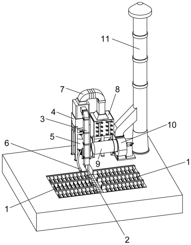
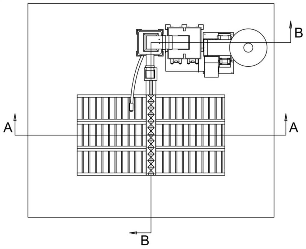
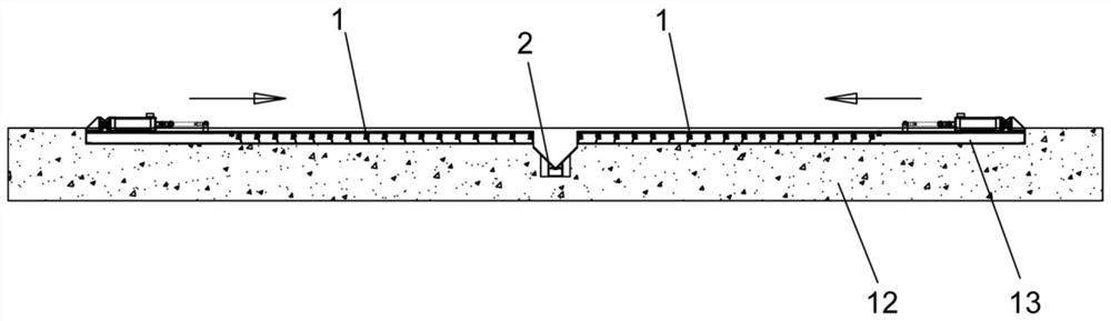
[0031] Such as Figure 1 to Figure 4 As shown, a composite granular material recovery device according to the present invention includes a particulate matter and powder material conveying equipment 1, a particulate matter collecting device 2, a conveying pipeline 3, a dust separator 4, a sandblasting tank 5, a spray gun 6, a suction Dust pipe 7, dust remover 8, dust removal pipe 9, centrifugal fan 10 and discharge pipe 11, the two sides of the particle collection device 2 are respectively provided with particle and powder conveying equipment 1, and the particles and powder on both sides of the particle collection device 2 The conveying equipment 1 can move towards the particle collection device 2 under the drive of the driving device. The discharge port of the particle collection device 2 is connected to the feed port of the conveying...


PUM


Abstract

The invention relates to the technical field of sand blasting processes, in particular to a combined type particle recycling device. The combined type particle recycling device comprises particle and powder conveying devices, a particle collecting device, a conveying pipeline, a sand-dust separator, a sand blasting tank, a spray gun, a dust suction pipe, a dust remover, a dust removal pipe, a centrifugal fan and a discharge pipe. The particle and powder conveying devices are arranged on the two sides of the particle collecting device correspondingly and can move towards the particle collecting device under driving of a driving device. The particle collecting device is connected to the conveying pipeline. The conveying pipeline is connected to the sand-dust separator. The sand-dust separator is connected to the sand blasting tank and the dust suction pipe. The sand blasting tank is connected to the spray gun. The dust suction pipe is connected to the dust remover. The dust remover is connected to the dust removal pipe. The dust removal pipe is connected to the centrifugal fan. The centrifugal fan is connected to the discharge pipe. The equipment foundation investment cost can be reduced, furthermore, the failure rate can be reduced, the shutdown maintenance time is shortened, and the equipment operation energy consumption is reduced.

Description

technical field [0001] The invention relates to the technical field of sand blasting process, in particular to a composite granular material recycling device. Background technique [0002] Sand blasting is powered by compressed air to form a high-speed jet beam to spray granular materials (copper ore, quartz sand, corundum, iron sand, sea sand) onto the surface of the workpiece to be treated at high speed, so that the outer surface of the workpiece surface looks or When the shape changes, due to the impact and cutting effect of the abrasive on the surface of the workpiece, the surface of the workpiece can obtain a certain degree of cleanliness and different roughness, so that the mechanical properties of the surface of the workpiece can be improved, thus improving the fatigue resistance of the workpiece and increasing the The adhesion between it and the coating prolongs the durability of the coating film, and is also conducive to the leveling and decoration of the coating. ...

Claims


Application Information

Patent Timeline
Patent Type & Authority Applications(China)
IPC IPC(8): B24C9/00B24C7/00
CPCB24C7/0046B24C9/003B24C9/006
Inventor 汪凤銮
Owner 汪凤銮
Why Eureka
Try Eureka