
GaN device and preparation method thereof

A device and gate technology, applied in the field of GaN devices and its preparation, can solve the problems of inability to reduce device on-resistance, affect power conversion efficiency, and reduce output power density

Pending Publication Date: 2021-05-18
SOUTH UNIVERSITY OF SCIENCE AND TECHNOLOGY OF CHINA
View PDF8 Cites 1 Cited by
  • Summary
  • Abstract
  • Description
  • Claims
  • Application Information

AI Technical Summary

Problems solved by technology

[0003] The on-resistance of GaN HEMT devices is a key indicator that affects device performance. For example, the on-resistance of GaN HEMT devices is large, which is reflected in the reduction of output power density in radio frequency devices, and the increase in conduction loss in power electronic devices, which affects the power supply. At the same time, the large on-resistance will cause high heat generation of the device, increase the cost of heat dissipation and even affect the reliability of the device
At present, the channel resistance of the epitaxial material is mainly reduced by increasing the two-dimensional electron gas concentration of the channel of the epitaxial material, increasing the gate length per unit area in terms of device design, and reducing the contact resistance of ohmic contact electrodes in terms of device technology. The on-resistance of radio frequency devices, when applying this kind of method, because the resistance of the material itself has reached about 250Ω, it is difficult to make a big breakthrough. To a certain extent, it is impossible to achieve a lower channel resistance of the epitaxial material, and then The on-resistance of the device cannot be reduced, and the manufacturing cost is high

Method used


Image

  • GaN device and preparation method thereof
  • GaN device and preparation method thereof
  • GaN device and preparation method thereof

Examples


Embodiment Construction

[0035] In order to make the object, technical solution and advantages of the present invention clearer, specific embodiments of the present invention will be further described in detail below in conjunction with the accompanying drawings. It should be understood that the specific embodiments described here are only used to explain the present invention, but not to limit the present invention.

[0036] In addition, it should be noted that, in order to further explain the technical means and effects of the present invention to achieve the intended purpose of the invention, a GaN device and its preparation method proposed according to the present invention will be described below in conjunction with the accompanying drawings and preferred embodiments. The specific embodiment, structure, feature and effect thereof are described in detail as follows.

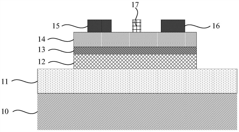
[0037] figure 1 A schematic structural diagram of a GaN device provided by an embodiment of the present invention. Such as figur...


PUM

PropertyMeasurementUnit
Thicknessaaaaaaaaaa

Abstract

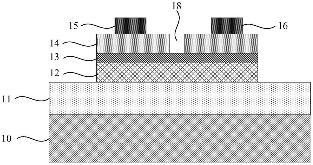
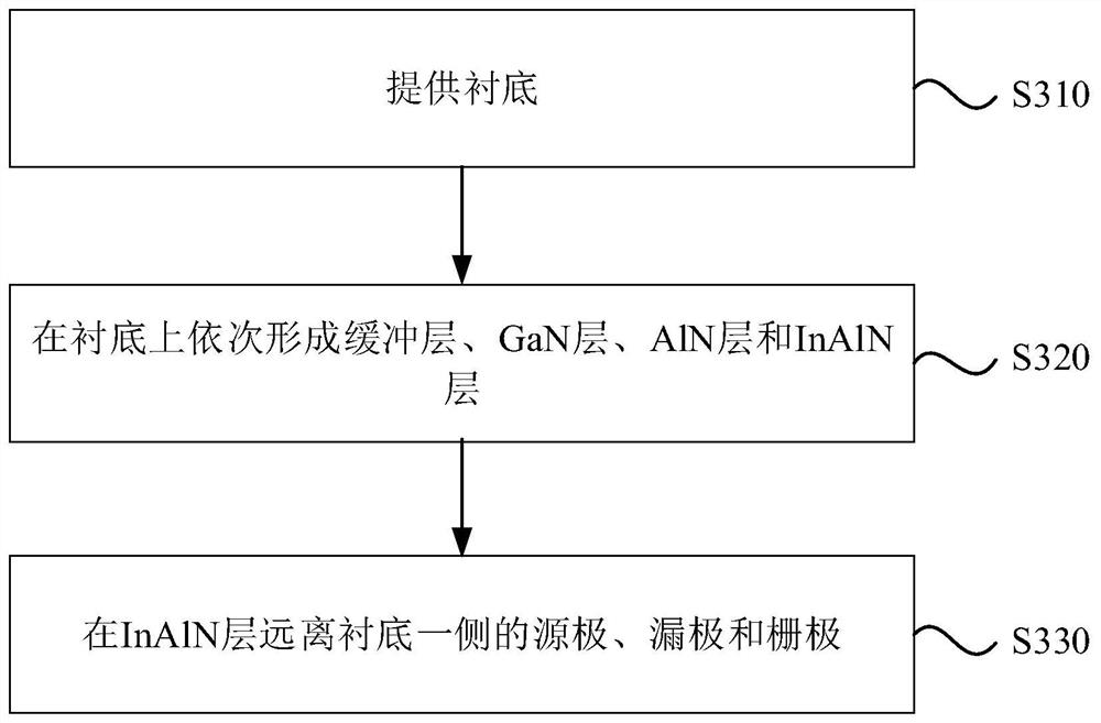
The embodiment of the invention discloses a GaN device and a preparation method thereof. The device comprises a substrate, a buffer layer, a GaN layer, an AlN layer, an InAlN layer, a source electrode, a drain electrode and a grid electrode, the substrate, the buffer layer, the GaN layer, the AlN layer and the InAlN layer are stacked in sequence, the source electrode, the drain electrode and the grid electrode are formed on the side, away from the substrate, of the InAlN layer, the source electrode and the drain electrode are of a Ti5Al1 and TiN stacked structure or a Ti5Al1 and W stacked structure, the material characteristics of Ti5Al1 and TiN and Ti5Al1 and W are utilized, the source electrode and the drain electrode are in contact with the GaN layer, the AlN layer and the InAlN layer, and the ohmic contact electrode is formed. The ohmic contact resistance is effectively reduced, so that the on-resistance of the GaN device is reduced, in addition, the normally-off GaN device is formed by using the ALE etching process, low-speed and low-loss etching is realized while the on-resistance is reduced, and meanwhile, the etching depth is accurately controlled, so that the grid electric leakage is effectively reduced, and the high withstand voltage value and the threshold voltage of the device are improved.

Description

technical field [0001] Embodiments of the present invention relate to the technical field of GaN radio frequency devices, in particular to a GaN device and a manufacturing method thereof. Background technique [0002] Gallium nitride (GaN) material has wide band gap, high breakdown electric field, high thermal conductivity, high electron saturation rate and higher radiation resistance, and is widely used in high temperature, high frequency, radiation resistance and high power semiconductor devices application prospects. GaN-based high electron mobility transistors (HEMTs) have been widely used in microwave communication and power electronic conversion and other fields. [0003] The on-resistance of GaN HEMT devices is a key indicator that affects device performance. For example, the on-resistance of GaN HEMT devices is large, which is reflected in the reduction of output power density in radio frequency devices, and the increase in conduction loss in power electronic device...

Claims


Application Information

Patent Timeline
IPC IPC(8): H01L29/778H01L21/335H01L29/06
CPCH01L29/7786H01L29/66462H01L29/0603H01L29/0684
Inventor 蒋洋于洪宇汪青郑韦志乔泽鹏范梦雅
Owner SOUTH UNIVERSITY OF SCIENCE AND TECHNOLOGY OF CHINA
Learn More