Plasma micro-beam coaxial electric polarization induced electronic jet printing device and jet printing method
A printing device and electric polarization technology, applied in printing and other directions, can solve the problems of difficulty in constructing electric field strength, turbulent jet flight trajectory, and space flight trajectory susceptible to external electromagnetic field interference, so as to achieve precise directional transportation, reduce airflow focusing, The effect of reducing jitters
- Summary
- Abstract
- Description
- Claims
- Application Information
AI Technical Summary
Problems solved by technology
Method used
Image

Examples
Embodiment Construction
[0032] In order to make the object, technical solution and advantages of the present invention clearer, the present invention will be further described in detail below in conjunction with the accompanying drawings and embodiments. It should be understood that the specific embodiments described here are only used to explain the present invention, not to limit the present invention. In addition, the technical features involved in the various embodiments of the present invention described below can be combined with each other as long as they do not constitute a conflict with each other.
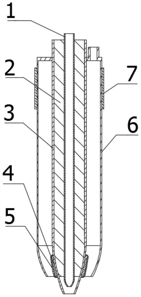
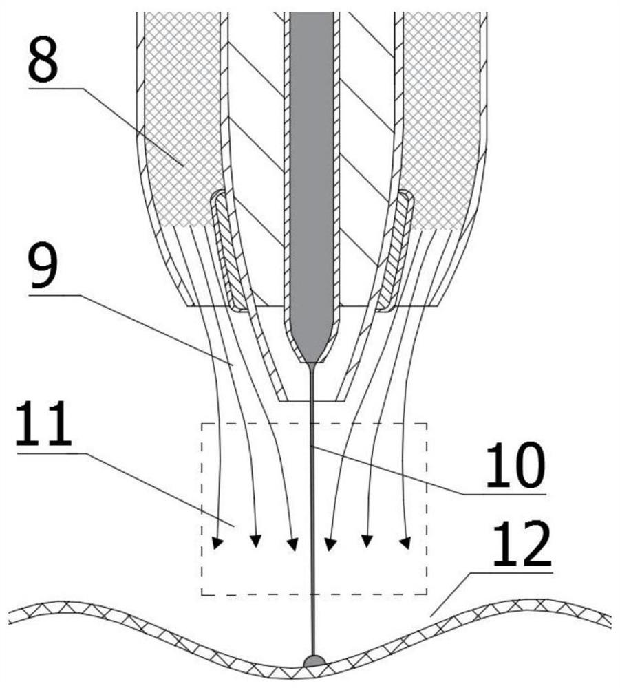
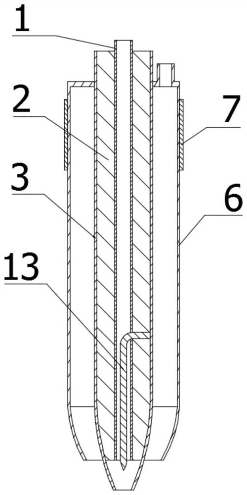
[0033] see figure 1 and figure 2 , the plasma micro-beam coaxial electric polarization-induced electrospray printing device provided by the present invention, the printing device includes an ink module, a plasma module and an induced electric field module, and the ink module is used to deliver the ink material for printing to the nozzle Among them, the plasma module is used to generate plasma...
PUM
 Abstract
Description
Claims
Application Information
 - R&D
- Intellectual Property
- Life Sciences
- Materials
- Tech Scout
- Unparalleled Data Quality
- Higher Quality Content
- 60% Fewer Hallucinations
Browse by: Latest US Patents, China's latest patents, Technical Efficacy Thesaurus, Application Domain, Technology Topic, Popular Technical Reports.
© 2025 PatSnap. All rights reserved.Legal|Privacy policy|Modern Slavery Act Transparency Statement|Sitemap|About US| Contact US: help@patsnap.com