
Regeneration system and method for synergistically removing multiple pollutants in flue gas

A regeneration system and pollutant technology, applied in separation methods, combustion methods, filter regeneration, etc., can solve the problems of increasing device operating costs, increasing equipment investment, and low wear and loss, and achieve reduced power consumption, low operating costs, and The effect of high degree of cleanliness

Pending Publication Date: 2021-06-04
HUANENG CLEAN ENERGY RES INST +1
View PDF10 Cites 0 Cited by
  • Summary
  • Abstract
  • Description
  • Claims
  • Application Information

AI Technical Summary

Problems solved by technology

[0002] The removal tower and the regeneration tower are the core equipment of the flue gas integrated purification technology of the activated coke dry method. The fixed bed removal tower and the moving bed removal tower are mostly used in industry. At present, due to the intermittent operation mode of the fixed bed removal tower The inability to adapt to the situation of dealing with large flue gas volumes promotes the widespread application of moving bed removal towers. However, when the existing moving bed technology is applied, the regeneration and desorption of the adsorbent has higher requirements than the removal of the pre-process. Regeneration and desorption The more thorough the sorbent, the greater the loading, the smaller the mobile cycle, and the lower the wear loss
[0003] At present, in the flue gas activated coke combined desulfurization and denitrification process, the active coke regeneration system mostly uses electric heaters or hot blast stoves to consume electric energy or gas as a heat source, which increases equipment investment, complicates the system and improves the operation of the entire device. cost

Method used


Image

  • Regeneration system and method for synergistically removing multiple pollutants in flue gas

Examples


Embodiment Construction

[0023] Embodiments of the present invention are described in further detail below:

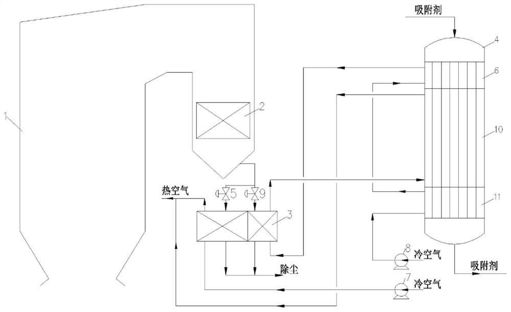
[0024] Such as figure 1 As shown, a regeneration system for synergistic removal of multi-pollutants in flue gas, including boiler 1, primary economizer 2, air preheater 3, regeneration tower 4, main flue baffle valve 5, preheating section 6 , Main air blower 7, regeneration air blower 8, regeneration flue gas regulating valve 9, heating section 10, cooling section 11.

[0025] The flue gas generated by the furnace of the boiler 1 is cooled by the primary economizer 2 and divided into two paths, one path is connected to the flue gas inlet of the main area of ​​the air preheater 3 through the main flue baffle valve 5, and the other path is regenerated The flue gas regulating valve 9 is connected to the flue gas inlet of the regeneration area of ​​the air preheater 3, and the two streams of cooled flue gas are collected to remove dust.

[0026] The air preheater 3 is divided into two areas, the...


PUM


Abstract

The invention discloses a regeneration system and method for synergistically removing multiple pollutants in flue gas; after boiler flue gas passes through a primary economizer, one path of flue gas is connected to a flue gas inlet of a main area of an air preheater, and the other path of flue gas is connected to a flue gas inlet of a regeneration area; one path of cold air is connected to an air inlet of the main area through a main air blower, and the other path of cold air is connected to an air inlet of a cooling section through a regenerated air blower; an air outlet of the cooling section is connected to an air inlet of a preheating section, an air outlet of the preheating section is connected to an air inlet of the regeneration area, and an air outlet of the regeneration area of the air preheater is connected to an air inlet of a heating section; and the air outlet pipeline of the heating section and the hot air outlet pipeline of the main area are gathered and then enter a boiler. The flue gas at the tail of the boiler is used for heating air for regeneration treatment of an adsorbent, heat is recycled in a stepped mode, utilization is sufficient, the operation cost is reduced, a back flushing system does not need to be additionally arranged, and the initial investment of the device is reduced.

Description

technical field [0001] The invention belongs to the technical field of flue gas pollutant treatment and purification, and in particular relates to a regeneration system and method for synergistic removal of multi-pollutants in flue gas. Background technique [0002] The removal tower and the regeneration tower are the core equipment of the flue gas integrated purification technology of the activated coke dry method. The fixed bed removal tower and the moving bed removal tower are mostly used in industry. At present, due to the intermittent operation mode of the fixed bed removal tower The inability to adapt to the situation of dealing with large flue gas volumes promotes the widespread application of moving bed removal towers. However, when the existing moving bed technology is applied, the regeneration and desorption of the adsorbent has higher requirements than the removal of the pre-process. Regeneration and desorption The more thorough the sorbent, the greater the loadin...

Claims


Application Information

Patent Timeline
IPC IPC(8): B01J20/34B01D53/08F23L15/00
CPCB01J20/3483B01D53/08F23L15/00B01D2258/0283Y02E20/34
Inventor 牛红伟樊启祥许世森郜时旺赵贺丹慧杰刘练波汪世清徐党旗
Owner HUANENG CLEAN ENERGY RES INST
Learn More